Image stabilization and shifting in a liquid crystal lens

a liquid crystal lens and image stabilization technology, applied in static indicating devices, instruments, non-linear optics, etc., can solve the problems of difficult to produce the required thickness of high resistivity materials, difficult to produce lc cells with good uniformity, and low yield of manufacturing processes, so as to reduce optical (image) aberrations, reduce the disclination of lc layers, and improve the performance of lenses.

Inactive Publication Date: 2015-05-19
POINT FINANCIAL
View PDF19 Cites 9 Cited by
  • Summary
  • Abstract
  • Description
  • Claims
  • Application Information

AI Technical Summary

Benefits of technology

[0008]It is an object of the proposed solution to provide improved (efficient) control over the movement of the focus of a tunable liquid crystal lens.
[0009]It has been discovered that improved (efficient) control of an electric field generated using a frequency dependent material can be provided using a segmented electrode to control the movement of the focus of the resulting lens.
[0022]The frequency dependent material can be selected to exhibit different charge mobility at different frequencies such that, at different frequencies, it can selectively (controllably) appear as a conductive or as a non-conductive material. For frequencies at which it appears as a conductor (high charge mobility), the frequency dependent material can create an effective electrode structure that is positioned differently than one of the fixed electrodes. However, for frequencies at which charge mobility in the frequency dependent material is relatively low, it does not appear as a conductor, and the effective electrode structure is determined by the actual position of the fixed electrodes. Thus, with proper positioning of a frequency dependent material, and the selection of different drive frequencies, the effective conductor configuration can be altered and the optical properties of the LC layer can be dynamically changed.
[0037]For example, an LC layer can be used that has a low angle pre-tilt alignment layer, and a first frequency can be applied for which the effective electrode structure is uniform. At this frequency, the voltage can then be increased to a level at which the LC molecules all have an initial reorientation at a uniform tilt. The frequency of the voltage can then be changed to modify the effective voltage structure and introduce non-uniformities into the electric field so as to change the optical characteristic of the liquid crystal, such as to form a lens structure. By applying an initial uniform electric field strength to the liquid crystal before introducing electric field non-uniformities, disclinations in the LC layer are minimized (avoided). The drive signal can also be applied so as to prevent the liquid crystal molecules from remaining close to a ground state, and to thereby reduce optical (image) aberrations. In another example, frequency control can be used to alter the optical power of an LC lens, but the voltage of the drive signal switched from one level to another at different optical powers so as to improve the performance of the lens. Many other similar control paradigms are likewise possible.

Problems solved by technology

Unfortunately, it is difficult to produce the required thickness of high resistivity material with high optical transparency, as well it is hard to produce an LC cell with good uniformity, and the manufacturing process typically has a low yield.
It is not possible to switch between a diverging and converging lens.
Unfortunately, the complex patterning of the top electrode, the necessity of using two distinct voltages and a separate WCL are difficult to manufacture and inhibit the practical use of this approach.
For example, the use of this approach to build a polarization independent lens would require the use of six to seven thick glass elements, which is a difficult task.

Method used


Image

  • Image stabilization and shifting in a liquid crystal lens
  • Image stabilization and shifting in a liquid crystal lens
  • Image stabilization and shifting in a liquid crystal lens

Examples


example

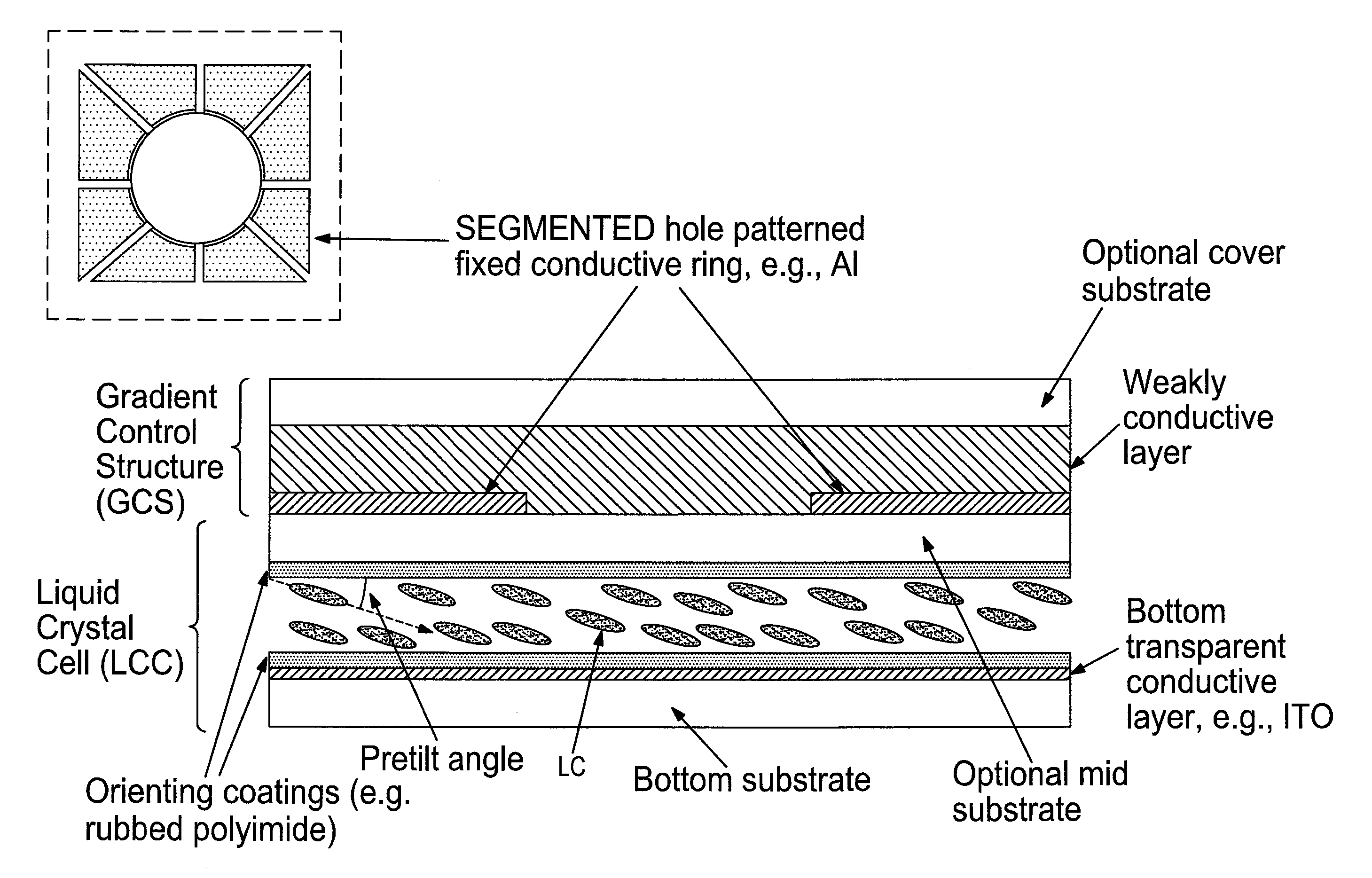
[0100]It will be appreciated that the tunable LC optical device can be fabricated using a layer by layer assembly and, preferentially, in a parallel way (many units simultaneously, referred to as “wafer level fabrication”), the final product being obtained by singulation and, optionally, joining lenses with operation axes (directors) in cross directions to focus two (both) orthogonal light polarizations.

[0101]By way of a non-limiting example, the dimensions of a variable focus flat refractive lens embodiment of the invention will be provided. It will be appreciated that dimensions can vary greatly depending on design choice and the choice of materials. The cover substrate can be made of glass with a thickness of 50 to 100 microns. The hole-patterned electrode can be made of an opaque metal such as aluminum, or it can be made of Indium Tin Oxide (ITO) which is transparent. The thickness of the electrode can be in the range of 10 to 50 nm. The frequency dependent material can be made ...


PUM

PropertyMeasurementUnit
dielectric constantaaaaaaaaaa
voltagesaaaaaaaaaa

Abstract

Variable liquid crystal devices for controlling the propagation of light through a liquid crystal layer use a frequency dependent material to dynamically reconfigure effective electrode structures in the device. The frequency of a drive signal that generates an electric field in the device can be varied, and the frequency dependent material has different charge mobilities for the different frequencies. At a low charge mobility, the frequency dependent material has little effect on the existing electrode structures. However, at a high charge mobility, the frequency dependent material appears as an extension of the fixed electrodes, and can be used to change the effective electrode structure and, thereby, the spatial profile of the electric field. This, in turn, changes the optical properties of the liquid crystal, thus allowing the optical device to be frequency controllable.

Description

TECHNICAL FIELD[0001]The present application is directed to liquid crystal lens devices.BACKGROUND OF THE INVENTION[0002]Tunable liquid crystal lenses are described for example, in commonly-owned PCT patent application WO2009 / 153764 published Dec. 23, 2009 wherein a tunable liquid crystal lens uses a frequency dependent material (as defined therein) to shape an electric field and a corresponding refractive index gradient within a liquid crystal cell, suitable for creating a lens.[0003]In the article titled “Liquid crystal lens with focus movable in focal plane” by Ye et al. published in Optics Communications, 259 (2006) 710-722, there is disclosed a liquid crystal lens in which the optical axis of the lens is movable by controlling the relative amplitudes of control signals applied to each quadrant of a four segment hole-patterned electrode. The lens arrangement uses the segmented electrode below a planar electrode, both electrodes which are fed a control signal to define the electr...

Claims


Application Information

Patent Timeline
Patent Type & Authority Patents(United States)
IPC IPC(8): G02F1/133G02F1/13G02F1/1343G02F1/1347G02F1/135G02F1/29
CPCG02F1/134309G02F1/135G02F1/13471G02F2001/294G02F2203/06G02F1/294G02F1/13439
Inventor GALSTIAN, TIGRANPRESNIAKOV, VLADIMIRASATRYAN, KARENZOHRABYAN, ARMEN
Owner POINT FINANCIAL
Why Eureka
Try Eureka