
Gate electrode with a shrink spacer

a gate electrode and shrink spacer technology, applied in the field of integrated circuits, can solve the problems of significant device variations, two-step patterning process for forming the mask features of the gate electrode structure may suffer from reduced scalability and controllability, and require complex techniques for finally obtaining resist features, etc., to achieve superior controllability and scalability, reduce lateral distance, and improve uniformity.

Inactive Publication Date: 2015-05-26
GLOBALFOUNDRIES INC
View PDF2 Cites 3 Cited by
  • Summary
  • Abstract
  • Description
  • Claims
  • Application Information

AI Technical Summary

Benefits of technology

The present patent enables manufacturing techniques for semiconductor devices with improved circuit features such as gate electrodes. These techniques provide better control and scalability over critical dimensions, resulting in smaller gate lengths and reduced lateral distances. These techniques also contribute to superior device uniformity and reduced overall process complexity compared to conventional methods.

Problems solved by technology

For example, presently, in critical lithography steps, an exposure wavelength of 193 nm may be used, which, therefore, may require complex techniques for finally obtaining resist features having dimensions well below the exposure wavelength.
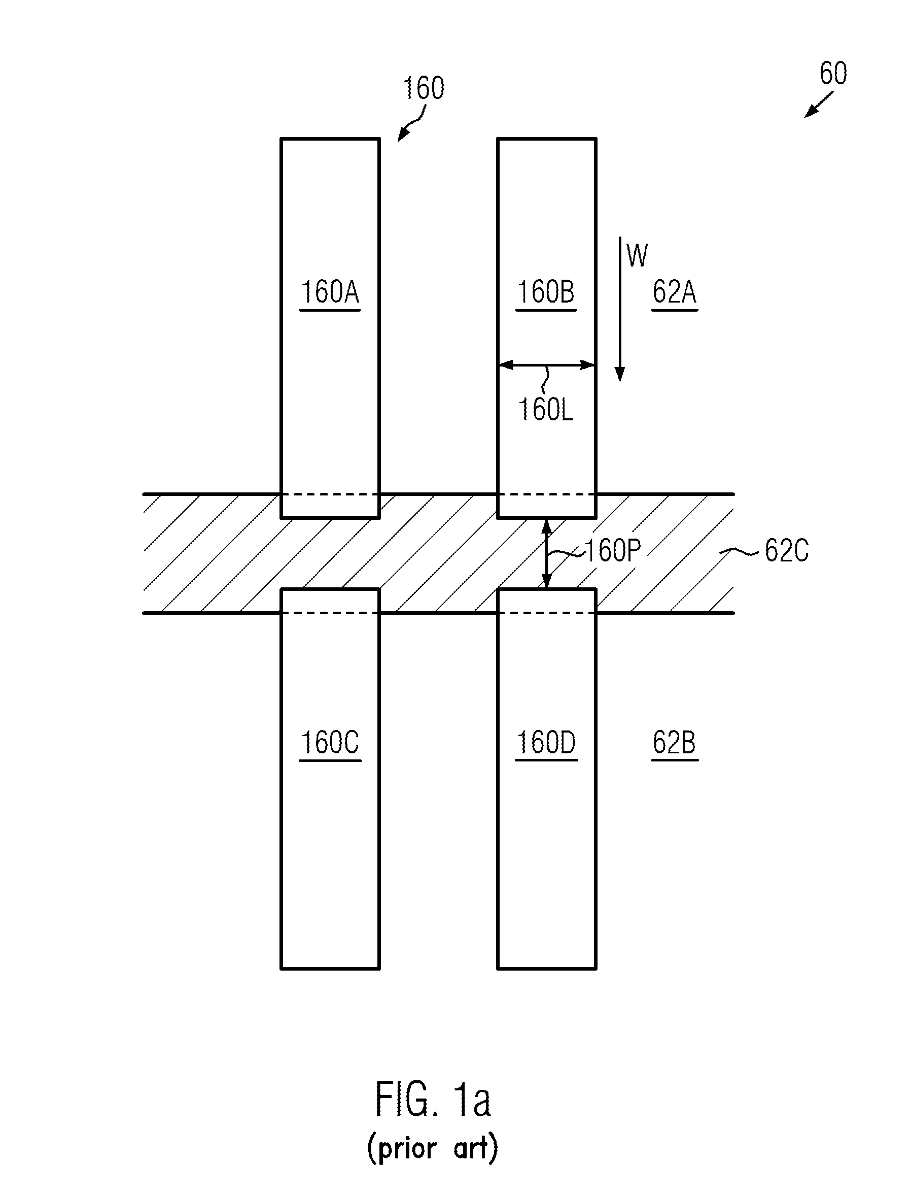
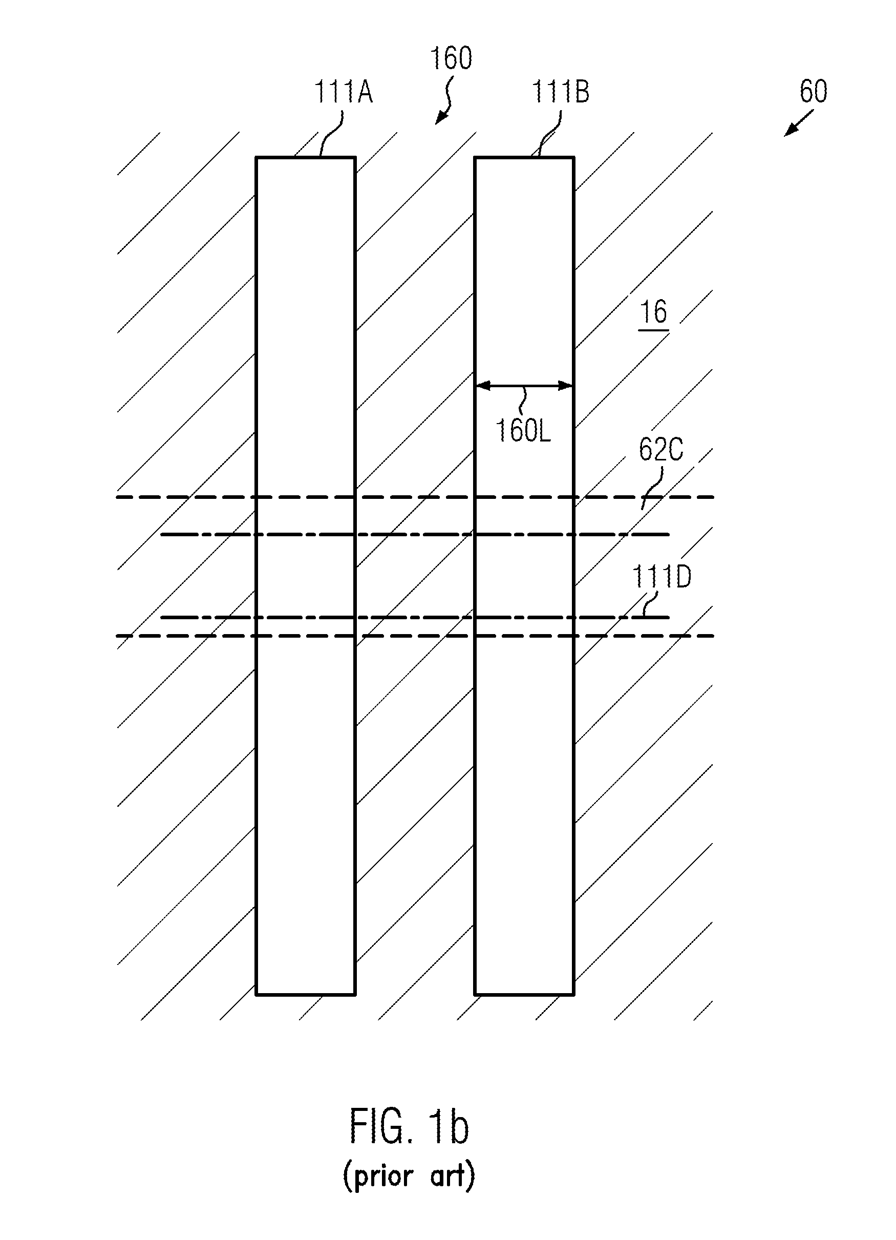
It turns out, however, that upon further shrinkage of the overall device dimensions, the two-step patterning process for forming the mask features for the gate electrode structures may suffer from reduced scalability and controllability, as will be described in more detail with reference to FIGS. 1a-1j.
On the other hand, sophisticated etch techniques, for instance using polymerizing gases during the etch process for transferring the opening 112O (FIG. 1f) into the underlying mask features may result in significant device variations, while other approaches, such as improving the resist materials and / or the optical imaging system, may require significant research and development improvements and any such improvements are not yet available.
However, it turned out that the mask opening involved in the taught procedure may undesirably leave some imprint in the polysilicon layer of the gate electrode of a transistor.
This imprint deteriorates the overall operation of the finished transistor / semiconductor device.

Method used


Image

  • Gate electrode with a shrink spacer
  • Gate electrode with a shrink spacer
  • Gate electrode with a shrink spacer

Examples


Embodiment Construction

[0033]Various illustrative embodiments of the invention are described below. In the interest of clarity, not all features of an actual implementation are described in this specification. It will of course be appreciated that in the development of any such actual embodiment, numerous implementation-specific decisions must be made to achieve the developers' specific goals, such as compliance with system-related and business-related constraints, which will vary from one implementation to another. Moreover, it will be appreciated that such a development effort might be complex and time-consuming, but would nevertheless be a routine undertaking for those of ordinary skill in the art having the benefit of this disclosure.

[0034]The present disclosure will now be described with reference to the attached figures. Various structures, systems and devices are schematically depicted in the drawings for purposes of explanation only and so as to not obscure the present disclosure with details whic...


PUM


Abstract

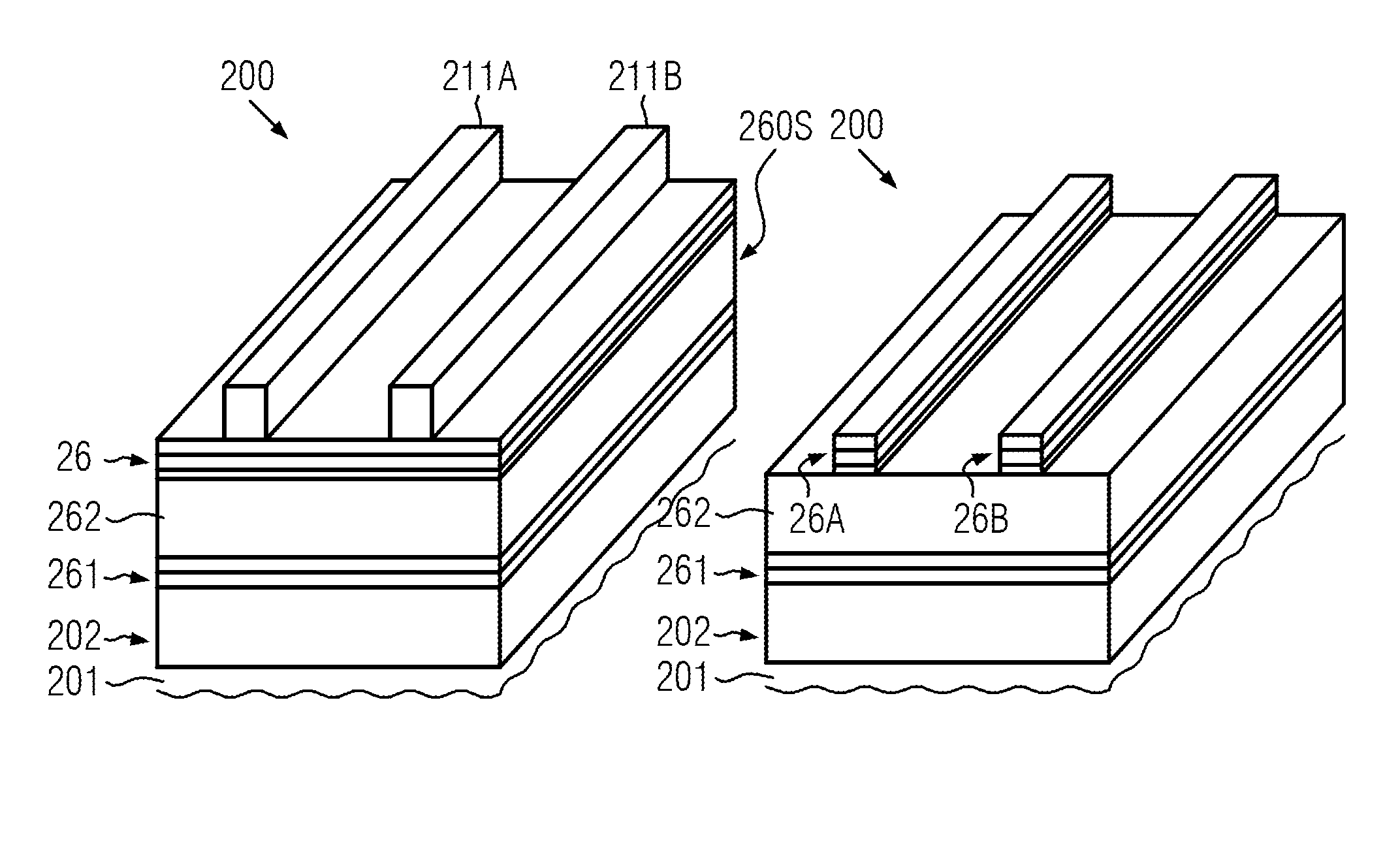
A method of forming a semiconductor device including forming a dielectric material layer on a semiconductor layer, forming a gate electrode material layer on the dielectric material layer, forming mask features on the gate electrode material layer, forming a spacer layer on and at sidewalls of the mask features and on the gate electrode material layer between the mask features, removing the spacer layer from the gate electrode material layer between the mask features, and etching the gate electrode material layer and dielectric material layer using the hard mask features as an etch mask to obtain gate electrode structures. A semiconductor device including first and second gate electrode structures, each covered by a cap layer that comprises a mask material surrounded at the sidewalls thereof by a spacer material different from the mask material, and the distance between the first and second electrode structures is at most 100 nm.

Description

BACKGROUND OF THE INVENTION[0001]1. Field of the Invention[0002]Generally, the subject matter disclosed herein relates to integrated circuits, and, more particularly, to gate electrode structures of transistor devices formed by double exposure and double etch techniques.[0003]2. Description of the Related Art[0004]The fabrication of microstructures, such as integrated circuits, requires tiny regions of precisely controlled size to be formed in one or more material layers of an appropriate substrate, such as a silicon substrate, an SOI (silicon-on-insulator) substrate or other suitable carrier materials. These tiny regions of precisely controlled size are typically defined by patterning the material layer(s) by applying lithography, etch, implantation and deposition processes and the like, wherein, typically, at least in a certain stage of the patterning process, a mask layer may be formed over the material layer(s) to be treated to define these tiny regions. Generally, a mask layer ...

Claims


Application Information

Patent Timeline
Patent Type & Authority Patents(United States)
IPC IPC(8): H01L21/3205H01L29/40H01L29/423
CPCH01L29/401H01L29/4232Y10S438/942Y10S438/947H01L21/0337H01L21/28123H01L21/32139H01L21/823437H01L21/823468
Inventor HASCHE, TOMBEYER, SVENLEMBACH, GERHARDEBERMANN, ALEXANDER
Owner GLOBALFOUNDRIES INC
Learn More