Anti-reflective lenses and methods for manufacturing the same
a technology of anti-reflective lenses and manufacturing methods, applied in the field of optical surfaces, can solve the problems of crazing of ar coatings either on the mold or on the lenses, and achieve the effect of avoiding high or elevated temperatures and good adhesion to the substra
- Summary
- Abstract
- Description
- Claims
- Application Information
AI Technical Summary
Benefits of technology
Problems solved by technology
Method used
Image

Examples
example 1
Cyclic Azasilanes
[0087]Various types of cyclic azasilanes can be used to practice the present invention, including:
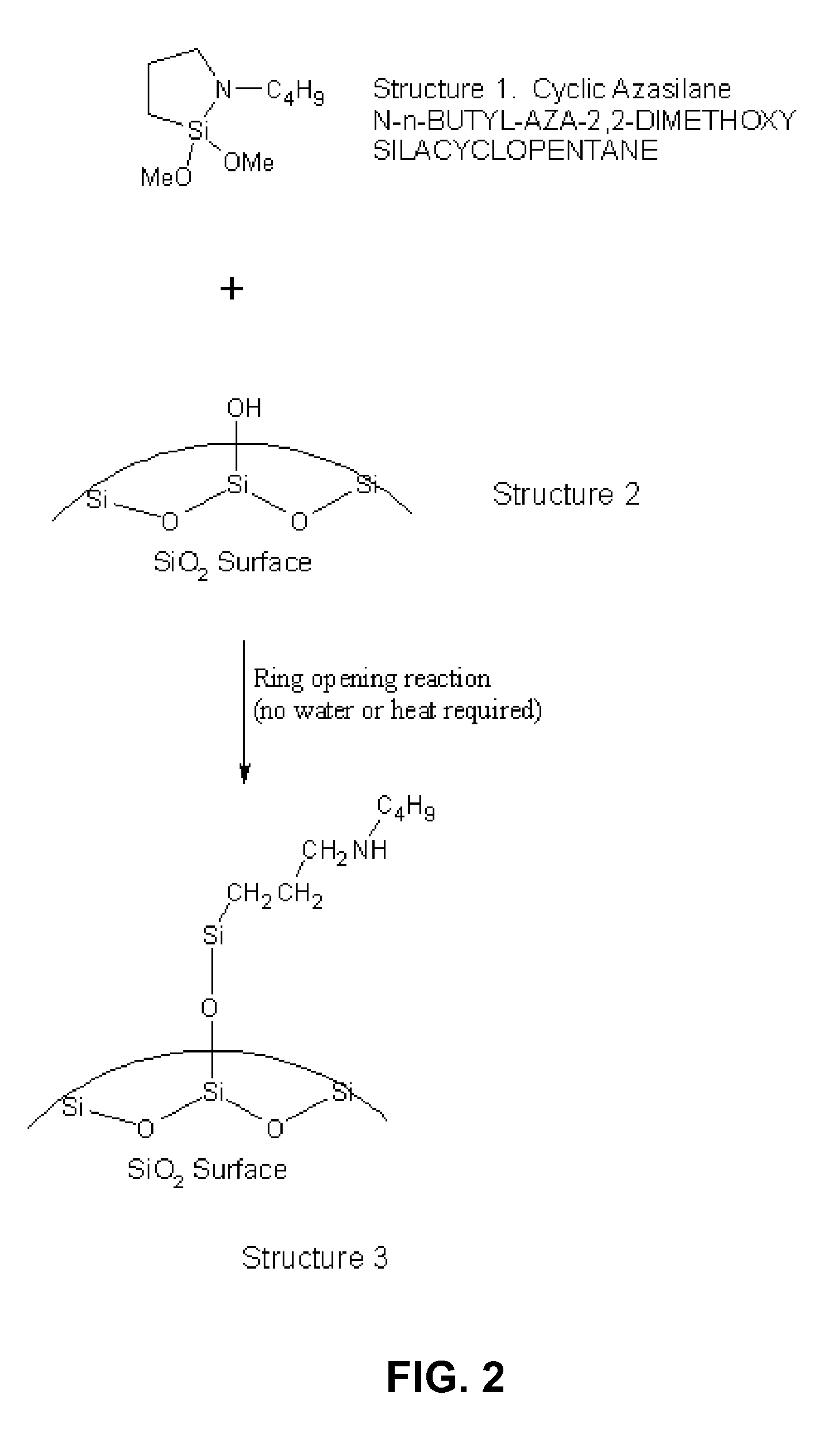
[0088](a) SIB1932.4 or N-n-BUTYL-AZA-2,2-DIMETIIOXYSILACYCLOPENTANE, C9H21NO2Si, with the following formula:
[0089]
[0090](b) SID3543.0 or 2,2-DIMETHOXY-1,6-DIAZA-2-SILACYCLOOCTANE, C7H18N2O2Si, with the following formula:
[0091]
[0092](c) SIA0592.0 or N-AMINOETHYL-AZA-2,2,4-TRIMETHYLSILACYCLOPENTANE, C8H21NSi, with the following formula:
[0093]
[0094](d) SIA0380.0 or N-ALLYL-AZA-2,2-DIMETHOXYSILACYCLOPENTANE C8H17NO2Si, with the following formula:
[0095]
example 2
Coating Bonding Tests
[0096]This example shows various tests utilized for the bonding of coatings produced according to various embodiments of the present invention.
[0097]Cross-Hatch Test. In the cross-hatch test, a series of 10 lines spaced 1 mm apart is cut into the coating with a razor blade. A second series of 10 lines spaced 1 mm apart at right angles to and overlaying the first is cut into the coating. A piece of cellophane tape is then applied over the crosshatch pattern and pulled quickly away from the coating.
[0098]Crazing Test. In the crazing test, a lens is de-molded then annealed at 80° C. for 20 minutes. The lens is quickly transferred to room temperature water and it is checked for crazing. If no crazing is apparent, then the AR / coupling agent system is acceptable.
[0099]Boiling Salt Water Test. In the boiling salt water test, the lens is first immersed for two minutes in a boiling salt solution containing 4.5% NaC1 and 0.8% NaH2PO4.2H2O. Next, the lens is quickly transf...
example 3
Preparation of an AR Coating that is Applied to a Disposable Mold
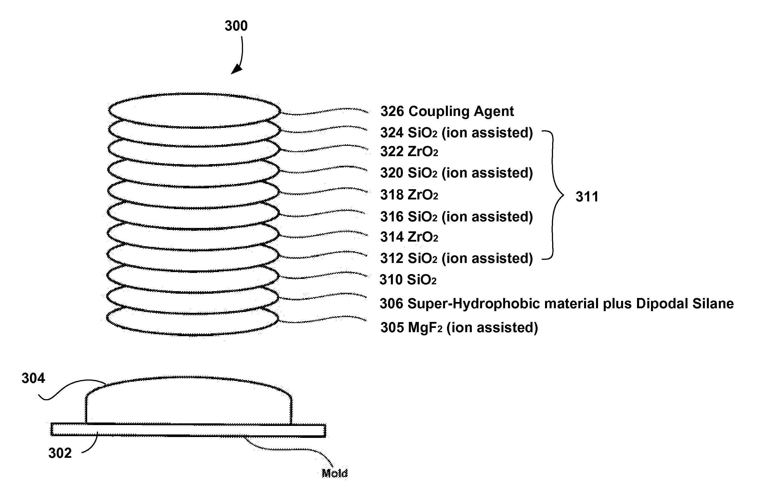
[0100]In this Example, among other things, a process of preparation of applying an AR coating to a disposable mold is provided according to one embodiment of the present invention. It is noted that in this Example, SiO2 layers are formed or deposited with or without ion assist.
[0101]Referring now to FIG. 3, the processes described below are performed with a standard box coater and an electron beam for evaporation in connection with a mold 302 having an optical surface 304. The processes are done by using well known vacuum practices.
[0102]Procedure:
[0103](1) Cleaning the optical surface 304 of the mold 302. In one embodiment of the present invention, a plasma cleaning is performed on the mold surface for about 2 min.
[0104](2) Forming a layer 305 of MgF2 with a thickness of about 45 nm to the optical surface 304.
[0105](3) Forming a layer 306 of a super hydrophobic material with a thickness of about 30 to 40 nm over the l...
PUM
| Property | Measurement | Unit |
|---|---|---|
| thickness | aaaaa | aaaaa |
| thickness | aaaaa | aaaaa |
| thickness | aaaaa | aaaaa |
Abstract
Description
Claims
Application Information
 - R&D
- Intellectual Property
- Life Sciences
- Materials
- Tech Scout
- Unparalleled Data Quality
- Higher Quality Content
- 60% Fewer Hallucinations
Browse by: Latest US Patents, China's latest patents, Technical Efficacy Thesaurus, Application Domain, Technology Topic, Popular Technical Reports.
© 2025 PatSnap. All rights reserved.Legal|Privacy policy|Modern Slavery Act Transparency Statement|Sitemap|About US| Contact US: help@patsnap.com