Dual energy solar thermal power plant

a solar thermal power plant and dual-source technology, applied in the direction of machines/engines, heat collector mounting/support, light and heating apparatus, etc., can solve the problems of unsatisfactory expectations, extreme dry air, bankers hesitant to commit capital to solar power plant projects, etc., to achieve low plant cost, reduce fuel cost, and build in a relatively short time

Active Publication Date: 2015-06-09
KUO CHANG
View PDF11 Cites 34 Cited by
  • Summary
  • Abstract
  • Description
  • Claims
  • Application Information

AI Technical Summary

Benefits of technology

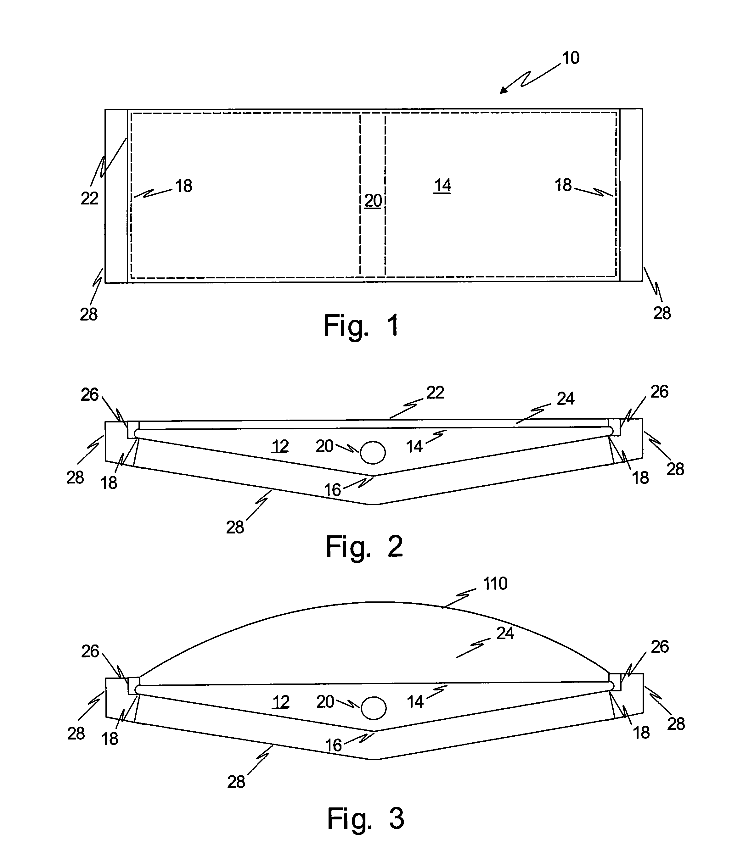
[0024]An alternative is to fill the gap with nitrogen gas instead of leaving the gap as a vacuum. At a certain degree of vacuum, a flat glass will break because of the atmospheric pressure. The nitrogen gas inside the gap will resist the atmospheric pressure, preventing the glass from breaking. Nitrogen gas is more stable than oxygen in the gap; hence, nitrogen gas will reduce the heat loss from the glass to atmosphere.
[0040]Because of the simplicity of design, this type of plant will have a much lower plant cost and can be built in a relatively short time. The savings in fuel cost as compared with a 600 MVA class coal fired power plant is about $24 million annually per plant. It would also reduce about 500,000 tons of emission of CO2 to the atmosphere per year. It will be able to resolve the safety problems of a nuclear power plant, because there is no radioactive material involved. The catastrophes of the Three-mile Island, the Chernobyl in Ukraine, and the Fukushima in Japan plants are well-known and horrible.

Problems solved by technology

This is because the region is a desert area, and the air is extremely dry.
However, the results have not met expectations.
Generally, bankers are hesitant to commit capital to solar power plant projects because the capital returns are less than anticipated.
This is a disadvantage for harnessing solar power.
The vast amount of solar energy that could be realized in this area has not been developed.
A huge amount of potential solar energy is being wasted every day.
Yet this is far below the 35% efficiency of a nuclear power plant, or 38% for a fossil power plant.
The majority of the solar energy is not effectively used by photovoltaic technology, as there are several disadvantages in the present photovoltaic technology.
First, the silicon film of its main component is delicate and expensive to manufacture.
The DC power generated in this system is not suitable for long-distance transmission to electrical power users because the DC current is not suitable for long distance transmission.
Each step of conversion increases power loss and adds to the overall cost.
The total equipment cost of a photovoltaic solar power system would be too high for a large power output, for example, from one to 300 mega-watts (MW) class power plant.
The plant would be economically prohibitive and the rate of solar energy utilization would be low.
The efficiency is also low.
Worse, under strong bombardment of ultra-violet (UV) radiation from the sun, the high cost silicon solar panels deteriorate rapidly.
Therefore, a large output photovoltaic power plant is not commercially practical today.
Those are examples of failed economical activities.
A solar power plant output of more than 300 MW is considered impractical considering that a large area of land is required and the cost is high.
The results are not encouraging.
Some have been abandoned and some are operating with high cost and low efficiency.
This is difficult to achieve by the proposed solar collector alone because the received solar rays alone cannot deliver quickly and consistently the large amounts of energy required to drive a turbine continuously.
Otherwise, it would not be practical for the capital investment.
It would not be feasible to build a solar thermal power plant if the equipment, labor and fuel costs are too high.
There have been too many high capital solar power plants abandoned because of high cost, low efficiency, or short duration of effective operation time.

Method used


Image

  • Dual energy solar thermal power plant
  • Dual energy solar thermal power plant
  • Dual energy solar thermal power plant

Examples


Embodiment Construction

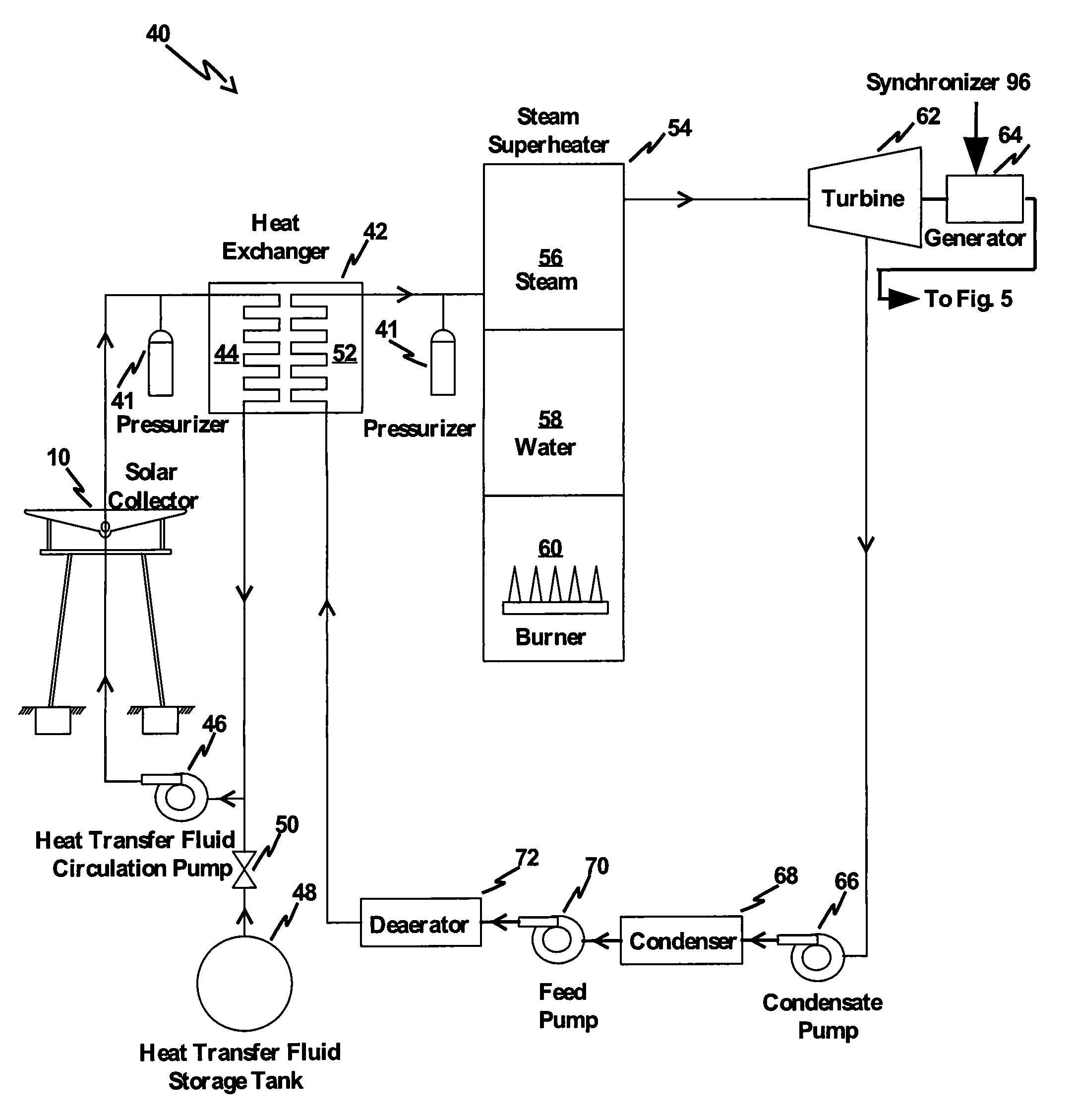
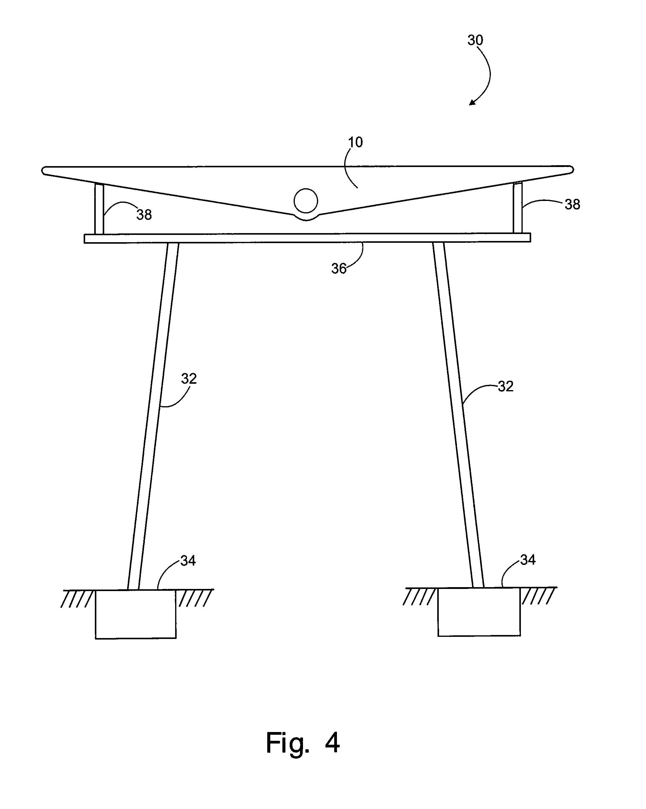
[0098]Persons of ordinary skill in the art will realize that the following description of the present invention is illustrative only and not in any way limiting. Other embodiments of the invention will readily suggest themselves to such skilled persons. Referring first to FIGS. 1 and 2: The diagrams show top and cross-sectional views, respectively, of an illustrative solar energy collector 10 in accordance with one aspect of the present invention. FIG. 3 shows the solar collector cross-sectional view if an arch type glass is used instead of a flat one as shown in FIG. 2.

[0099]The solar energy collector 10 comprises a solid body 12 having a substantially flat planar solar energy absorbing collecting surface 14. The body 12 is formed from an efficient heat conductive material, yet the cost is low enough to make the power plant feasible. The planar solar energy absorbing collecting surface 14 should be configured to maximize energy absorption. In some embodiments of the invention, the ...


PUM


Abstract

A design of a dual energy solar thermal power plant is proposed. It can be built on a piece of land where sunshine is abundant and the moisture in the air is relatively low. The desert corridor starting at Las Vegas and to the south is the best in the whole U.S. The power plant design is simple, using the equipment and material commonly available at reasonable costs. No particularly complicated equipment and material are required. The optimized plant size will be one MVA up to 300 MVA depending on the available land size in acres. The transmission line voltage can be from 13.8 kV up to 230 kV, depending on the MVA capacity. The land for a plant can be up to 600 acres.

Description

[0001]This application is a continuation in part of inventor Chang Kuo's Ser. No. 13 / 871,960 Dual Energy Solar Thermal Power Plant, filed Apr. 26, 2013, the disclosure of which is incorporated herein by reference, which in turn is a continuation in part of U.S. application Ser. No. 13 / 251,937 entitled Dual Energy Solar Power Plant filed Oct. 3, 2011, by same inventor Chang Kuo the disclosure of which is incorporated herein by reference.BACKGROUND[0002]1. Field of the Invention[0003]The present invention relates to the design of a dual source solar and thermal power generation plant that provides practical yet reliable power generation at low cost. In particular, the present invention relates to the design of a power plant with solar collectors and associated thermal power generating equipment, utilizing the proposed particular solar energy collectors, pressurizers, heat exchanger, auxiliary boiler / steam superheater, turbine-generator, generator frequency synchronizer, step-up transf...

Claims


Application Information

Patent Timeline
Patent Type & Authority Patents(United States)
IPC IPC(8): B60K16/00F03G6/00F24J2/24F24J2/50F24J2/52F24S10/70
CPCF03G6/00F03G6/005F24J2/242F24J2/50Y02E10/44Y02E10/46F24J2/5233F24J2/525F03G6/067F24S10/72F24S25/13F24S25/617F24S80/50F24S80/58
Inventor KUO, CHANG
Owner KUO CHANG
Why Eureka
Try Eureka