Resonant converter control based on a voltage difference

a technology of resonance converter and voltage difference, applied in the direction of electric variable regulation, process and machine control, instruments, etc., can solve the problems of reducing efficiency at low load, drawback of relatively large circulating current, and insufficient stored energy in the magnetizing inductance to provide soft switching, etc., to achieve the effect of simplifying the circui

Active Publication Date: 2015-06-23
NXP BV
View PDF31 Cites 24 Cited by
  • Summary
  • Abstract
  • Description
  • Claims
  • Application Information

AI Technical Summary

Benefits of technology

[0014]By controlling the predetermined voltage difference, an amount of energy input to the resonance circuit (or resonant tank) is controlled. Together with the resulting switching frequency, this determines the power output of the resonant power converter. An advantage of the invention therefore is that the power output can be controlled by altering this voltage difference, which can overcome existing problems relating to frequency control.
[0015]A further advantage of the invention is that, because a voltage difference is used rather than an absolute voltage for determining the conduction intervals, DC offset levels are not required. This makes the use of resistive dividers unnecessary, thereby simplifying the circuit.
[0016]The resonant power converter may have a half bridge or full bridge topology. In the case of a half bridge resonant power converter, the resonance circuit is connected between the node connecting the first and second switches and the ground line. In the alternative case of a full bridge resonant power converter, the resonance circuit is connected between the node connecting the first and second switches and a further node connecting third and fourth switches comprising a second half bridge of the full bridge instead of ground.
[0017]Where the conduction interval is a first conduction interval, the sampled voltage level is a first sampled voltage level and the predetermined voltage difference is a first predetermined voltage difference, the method may further comprise the repeated sequential steps of:
[0018]closing the second switch to start a second conduction interval;
[0019]sampling a voltage across the capacitor to obtain a second sampled voltage level; and

Problems solved by technology

Because of the large value of the magnetizing inductance of the series resonant converter 100, the stored energy in the magnetizing inductance is not sufficient to provide for soft switching.
For low loads, however, there is a drawback of a relatively large circulating current.
This results in a decreased efficiency at low load.

Method used


Image

  • Resonant converter control based on a voltage difference
  • Resonant converter control based on a voltage difference
  • Resonant converter control based on a voltage difference

Examples


Embodiment Construction

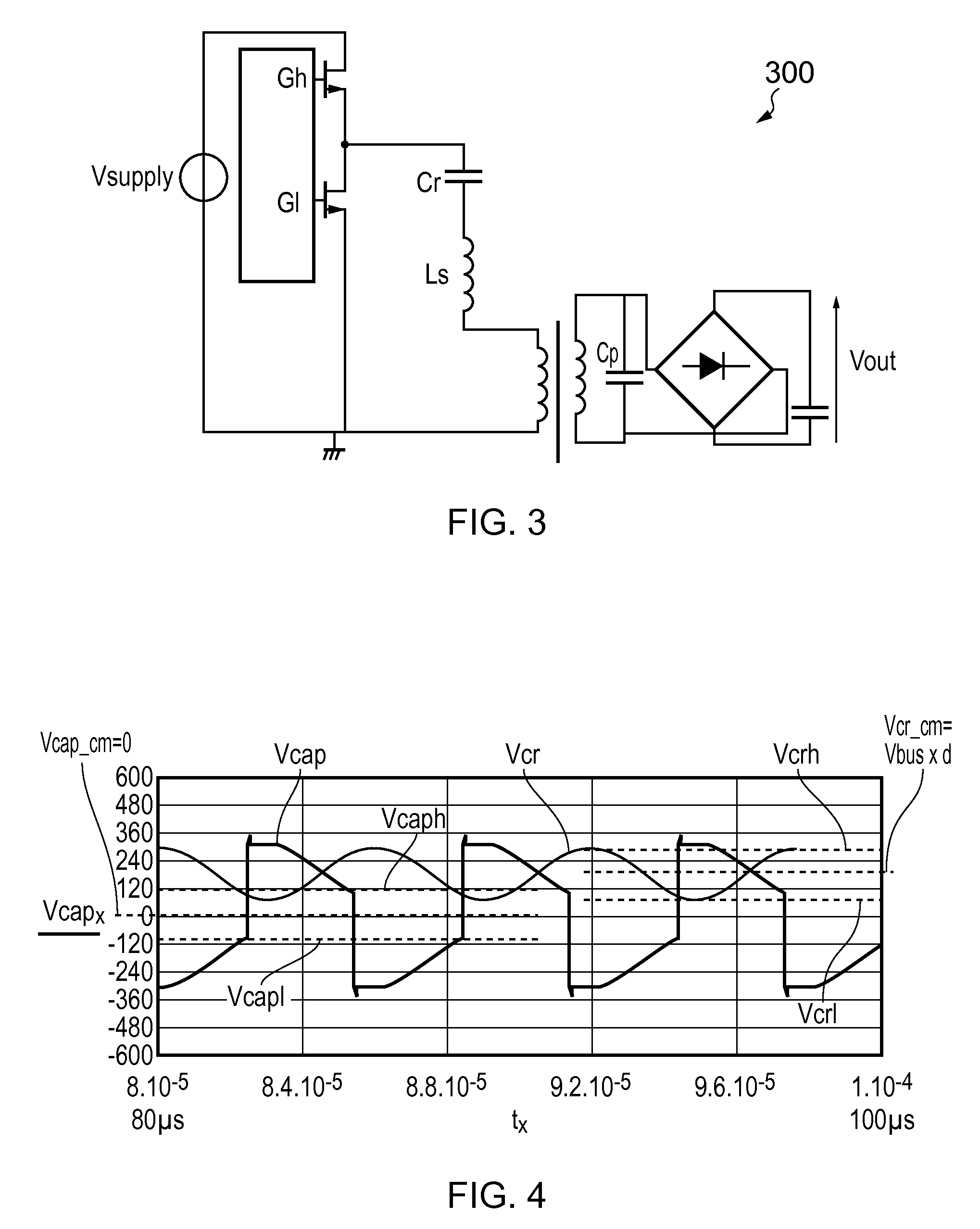
[0068]For control of the mode of operation of a resonant converter, an optimum timing of how the switches are operated needs to be determined. This can be an iterative process that requires a practical solution. One possible method can be illustrated using a so-called state plane representation, in which the voltage across a resonant capacitor is plotted against the current in the resonant tank. Using state plane representations, methods can be derived for controlling the resonant converter. One such method is capacitor voltage control, which involves controlling the way in which the switches are operated dependent on a sensed voltage across a capacitor forming part of the resonance circuit. According to this method, a voltage across the resonant capacitor is used to determine the timing for the switches that control the voltage across the resonant tank. Another method, optimum trajectory control, may be used in which the state plane trajectory, i.e. the relation between the capacit...


PUM


Abstract

Consistent with an example embodiment there is a method of controlling a resonant power converter; the power converter includes first and second series connected switches connected between a supply voltage line and a ground line and a resonance circuit, having a capacitor and an inductor. The resonance circuit is connected to a node connecting the first and second switches. The method comprises repeated sequential steps of closing the first switch to start a conduction interval; sampling a voltage across the capacitor to obtain a sampled voltage level; and opening the first switch to end the conduction interval when a voltage across the capacitor crosses a voltage level determined by addition of the sampled voltage level with a predetermined voltage difference; wherein controlling the predetermined voltage difference determines a power output of the resonant power converter.

Description

[0001]This application claims the priority under 35 U.S.C. §119 of European patent application no. 11250660.5, filed on Jul. 15, 2011, the contents of which are incorporated by reference herein.[0002]The invention relates to methods of controlling operation of a resonant power converter and to controllers configured to operate according to such methods.BACKGROUND OF THE INVENTION[0003]For electrical power converters operating at power levels larger than around 100 W at full load, a resonant topology is useful due to its high efficiency, small volume and high power density. At these power levels, the extra cost of resonant converters compared with other converters is compensated for by the additional advantages of a resonant topology. There are several types of resonant converters, using either half bridge or full bridge configurations, and the number of resonant components may vary.[0004]A general circuit diagram of a series resonant converter 100 is illustrated in FIG. 1. The conve...

Claims


Application Information

Patent Timeline
Patent Type & Authority Patents(United States)
IPC IPC(8): H02M3/337H02M1/00
CPCH02M3/3376Y02B70/1433H02M2001/0058Y02B70/1491H02M1/0058Y02B70/10
Inventor HALBERSTADT, HANS
Owner NXP BV
Why Eureka
Try Eureka