Apparatus for combusting a fuel at high pressure and high temperature, and associated system

a technology of combusting fuel and apparatus, which is applied in the direction of combustion types, lighting and heating apparatus, separation processes, etc., can solve the problems of reducing the flow rate of volumetric fluid, reducing capital costs, and reducing equipment size, so as to enhance the oil recovery and enhance the effect of natural gas production or disposal, power saving

Active Publication Date: 2015-06-30
8 RIVERS CAPTTAL LLC
View PDF64 Cites 95 Cited by
  • Summary
  • Abstract
  • Description
  • Claims
  • Application Information

AI Technical Summary

Benefits of technology

[0011]In another aspect, oxy-fuel combustion of carbonaceous fuels (and / or hydro-carbonaceous fuels) may also involve the separation of substantially pure oxygen from air (or otherwise providing such substantially pure oxygen) and its use as in the combustion process to produce combustion products which are substantially free of nitrogen and which comprise carbon dioxide and water vapor. The carbon dioxide-rich combustion product (following cooling and water condensation) may then be available for subsequent commercial use, such as for enhanced oil recovery or enhanced natural gas production or disposal in a suitable geological sequestration site (following compression and purification). Operation of an oxy-fuel power production system at high pressure may also allow the carbon dioxide derived from the fuel to be produced at a high pressure, resulting in power savings by reducing or eliminating the need to pressurize the carbon dioxide. Further, high pressure operation may allow the purified combustion products to be used directly in a power cycle, when mixed with a suitable heated working fluid such as CO2 or steam. The operation of the power system at high pressure may also lead to reduced volumetric fluid flow rates in the power cycle, resulting in smaller equipment and lower capital costs. The high pressure oxy-fuel combustor with provision for temperature control is another important aspect. Cycling of a suitable fluid such as combustion product gas or carbon dioxide or liquid water or steam (such as from a recycle stream) through a transpiration-cooled and protected wall of the combustion chamber / space may also serve to control the combustion temperature. Flow of the transpiration fluid through the combustion chamber walls may also serve to eliminate damage to and / or build-up on the chamber walls due to heat, or ash or liquid slag impingement effects. Thus, an efficient high pressure, high temperature combustor is provided which can be adapted to burn a variety of gaseous, liquid, or solid fuels or fuel mixtures to meet various requirements as part of a power system which can operate at significantly higher efficiencies and lower capital costs than present technology. In some instances, the combustor may be operated to produce a combustion product comprising hydrogen and carbon monoxide to be made available to downstream requirements, other than power production.
[0013]In aspects involving power production, a portion of a working fluid is introduced into the combustor, along with the fuel and oxidant (i.e., enriched oxygen), for combustion, such that a high pressure, high temperature fluid stream (combustion product) is produced comprising the working fluid and the combustion products. The working fluid can be introduced through the transpiration-protected walls of the combustion chamber and / or through additional injection points about the combustion chamber. The working fluid, following the combustion process and mixing with the combustion products through transpiration, may have a temperature in a range suitable (i.e., low enough) for introduction directly into a power generation device, such as a turbine. In such instances, the total quantity of working fluid introduced into the combustor, as a diluent to the combustion products, may be adjusted to provide an exit temperature for the total working fluid stream leaving the combustor which is suitable for the operating inlet temperature and pressure of the power turbine. Advantageously, the fluid stream may be maintained at a relatively high pressure during expansion in the turbine such that the pressure ratio across the turbine (i.e., the ratio of the pressure at the inlet to the pressure at the outlet of the turbine) is less than about 12. The fluid stream can also be further processed to separate the components of the fluid stream, wherein such processing can include passing the fluid stream through a heat exchanger. In particular, the expanded working fluid (at least a portion of which may be recycled from the fluid stream) can be passed through the same heat exchanger to heat the high pressure working fluid prior to introduction of the same into the combustor. In certain aspects, the disclosure provides a high pressure oxy-fuel combustor for power production systems that can produce power at high efficiency with low capital cost and also can produce substantially pure CO2 at pipeline pressure for commercial use or sequestration. The CO2 also may be recycled into the power production system.
[0016]In still another aspect, the present disclosure may provide the ability to reduce the physical size and capital cost of a power generation system compared to current technologies using a similar fuel. Thus, the methods and systems of the present disclosure can contribute to or otherwise facilitate significantly reduced construction costs associated with power production systems, and the relatively high efficiency of certain system combinations can lead to reduced costs of electricity or energy production, as well as reduced use of fossil fuels.

Problems solved by technology

The operation of the power system at high pressure may also lead to reduced volumetric fluid flow rates in the power cycle, resulting in smaller equipment and lower capital costs.

Method used


Image

  • Apparatus for combusting a fuel at high pressure and high temperature, and associated system
  • Apparatus for combusting a fuel at high pressure and high temperature, and associated system
  • Apparatus for combusting a fuel at high pressure and high temperature, and associated system

Examples


Embodiment Construction

[0037]The present disclosure now will be described more fully hereinafter with reference to the accompanying drawings, in which some, but not all aspects of the disclosure are shown. Indeed, this disclosure may be embodied in many different forms and should not be construed as limited to the aspects set forth herein; rather, these aspects are provided so that this disclosure will satisfy applicable legal requirements. Like numbers refer to like elements throughout.

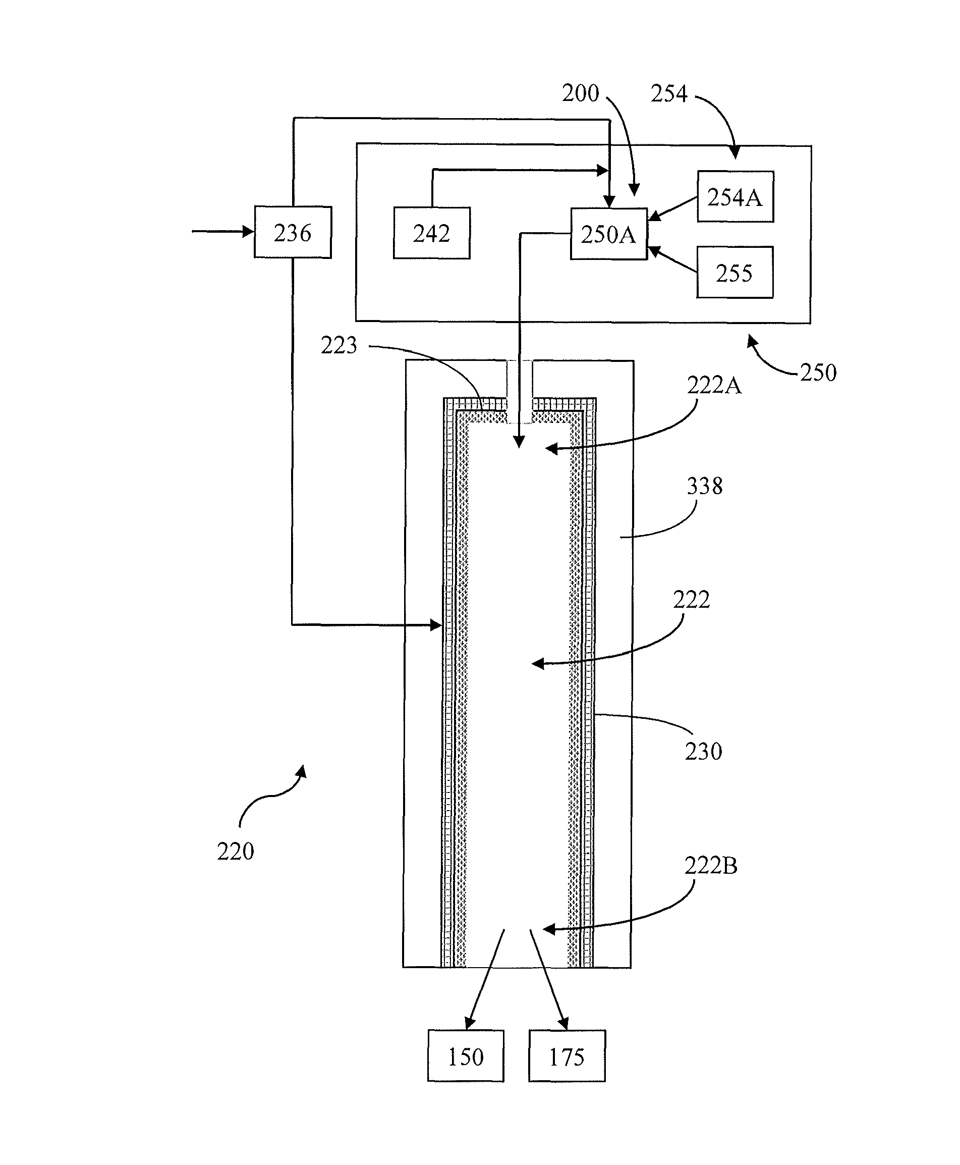
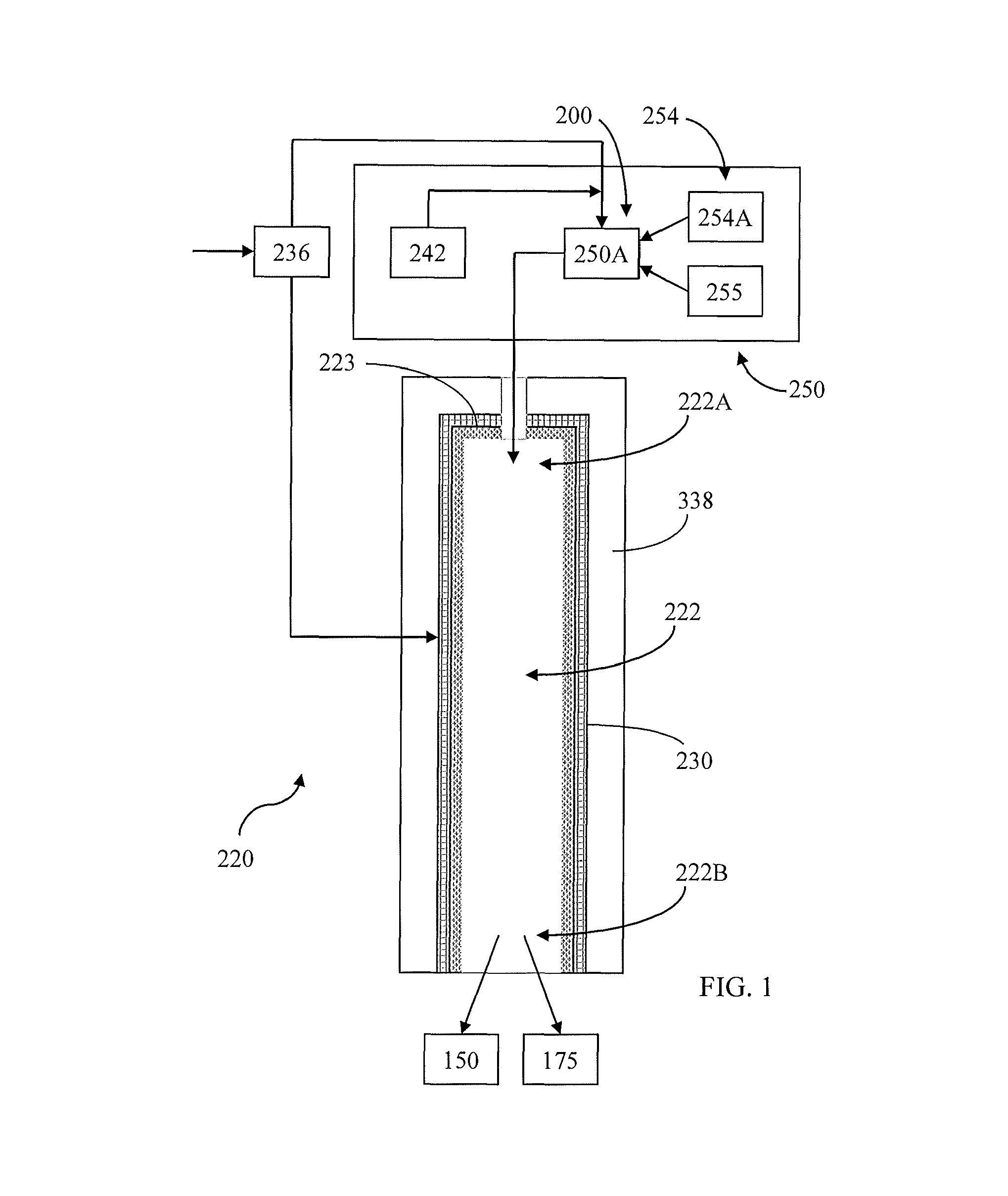
[0038]One aspect of a combustor apparatus capable of operating with a solid fuel, according to the present disclosure, is schematically illustrated in FIG. 1, the combustor apparatus being generally indicated by the numeral 220. In this example, the combustor apparatus 220 may be configured to combust a particulate solid such as coal to form a combustion product, though any other suitable combustible organic material, as disclosed herein, may also be used as a fuel. The combustion chamber 222 may be defined by a transpirat...


PUM


Abstract

A combustor apparatus is provided, comprising a mixing arrangement for mixing a carbonaceous fuel with enriched oxygen and a working fluid to form a fuel mixture. A combustion chamber is at least partially defined by a porous perimetric transpiration member, at least partially surrounded by a pressure containment member. The combustion chamber has longitudinally spaced apart inlet and outlet portions. The fuel mixture is received by the inlet portion for combustion within the combustion chamber at a combustion temperature to form a combustion product. The combustion chamber further directs the combustion product longitudinally toward the outlet portion. The porous transpiration member is configured to substantially uniformly direct a transpiration substance laterally therethrough, about the perimeter thereof defining the combustion chamber and longitudinally between the inlet and outlet portions, toward the combustion chamber for buffering interaction between the combustion product and the porous transpiration member. Associated systems are also provided.

Description

CROSS-REFERENCE TO RELATED APPLICATIONS[0001]The present patent application is a continuation-in-part of U.S. patent application Ser. No. 12 / 714,074, filed Feb. 26, 2010, which claims priority to U.S. Provisional Patent Application No. 61 / 155,755, filed Feb. 26, 2009, and U.S. Provisional Patent Application No. 61 / 299,272, filed Jan. 28, 2010, the disclosures of which are all incorporated herein by reference in their entirety.BACKGROUND OF THE DISCLOSURE[0002]1. Field of the Disclosure[0003]The present disclosure is directed to apparatuses and systems for the combustion of a carbonaceous fuel with oxygen at high pressure and high temperature to produce combustion products which are either oxidized with an excess of oxygen, or which contain reducing components and have zero oxygen content. One particular application would be for generation of energy, such as electricity, through the use of a working fluid to transfer energy generated through high efficiency combustion of a fuel. Part...

Claims


Application Information

Patent Timeline
Patent Type & Authority Patents(United States)
IPC IPC(8): F23C7/00B01D53/34B01J19/00F23J15/02F23L7/00F23M5/08F23G7/06F23D1/00F23R3/00
CPCF23D1/00F23G7/065B01D53/34B01J19/00F23J15/027F23L7/002F23L7/007F23M5/08F23R3/002F23L2900/07001F23L2900/07002F23L2900/07003F23L2900/07007F23L2900/07008F23M2900/05004F23R2900/03041Y02E20/322Y02E20/344Y02E20/12Y02E20/32Y02E20/34
Inventor PALMER, MILES R.ALLAM, RODNEY JOHNBROWN, JR., GLENN WILLIAM
Owner 8 RIVERS CAPTTAL LLC
Why Eureka
Try Eureka