
Induction type power supply system with synchronous rectification control for data transmission

a technology of synchronous rectification control and power supply system, which is applied in the direction of electric variable regulation, process and machine control, instruments, etc., can solve the problems of high power transmission interference, unexpected risk, and difficulty in stabilizing the transmission of feedback data signal from the coil, so as to reduce the amplitude of the signal, avoid component damage, and increase the amplitude of the supplying end coil

Active Publication Date: 2015-07-07
FU TONG TECH
View PDF60 Cites 18 Cited by
  • Summary
  • Abstract
  • Description
  • Claims
  • Application Information

AI Technical Summary

Benefits of technology

[0008]The present invention has been accomplished under the circumstances in view. It is one object of the present invention to provide an induction type power supply system with synchronous rectification control for data transmission, which assures a high level of data signal transmission stability and a high level of power transmission efficiency.
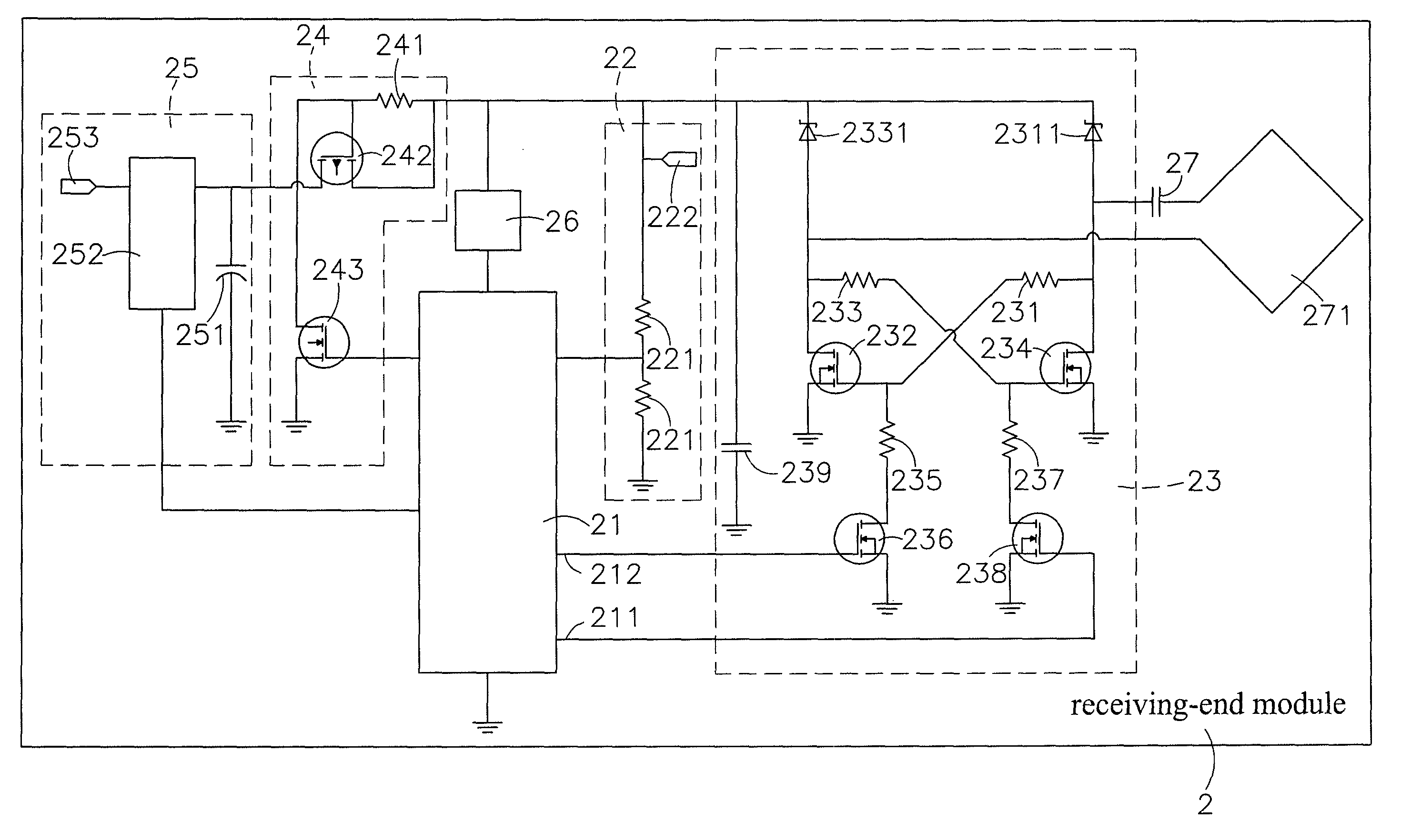
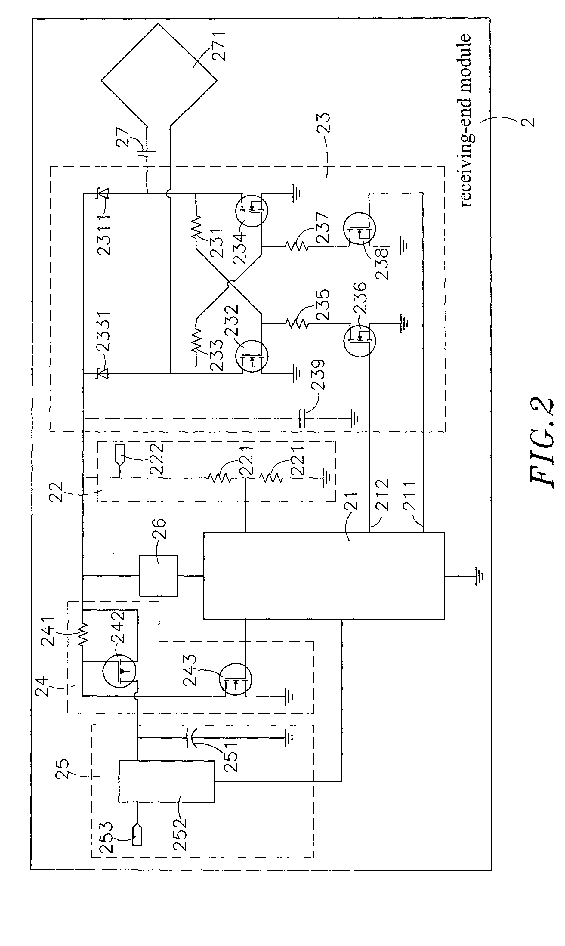
[0009]To achieve this and other objects of the present invention, an induction type power supply system with synchronous rectification control for data transmission comprises a supplying-end module and a receiving-end module. The receiving-end module receives power supply from the supplying-end coil, and provides a feedback data signal to the supplying-end coil during power supply transmission subject to the operation of a rectifier and signal feedback circuit of the receiving-end module that breaks off electric current transiently to change the load characteristics of the receiving-end coil, allowing transmission of the feedback data signal without causing power loss.
[0011]Further, during induction between the supplying-end coil of the supplying-end module and the receiving-end coil of the receiving-end module, inducted electric current is transmitted by the supplying-end module to the receiving-end module. At this time, the receiving-end module is regarded as a load, which receives electric current from the supplying-end coil, and the current volume will affect the amplitude of the supplying-end coil. Further, a control switch is designed and installed in the rectifier and signal feedback circuit to break of electric current. By means of switching off the rectifier and signal feedback circuit to disconnect the load from the supplying-end module transiently, the supplying-end coil is controlled to run idle, thereby reducing signal amplitude. During interruption of power transmission, the power of the capacitor at the rear end drops. When the rectifier and signal feedback circuit is switched on again, the capacitor is charged, thereby increasing the amplitude of the supplying-end coil. By means of this effect, the power-supply module can feed back data signal to the supplying-end module without causing a significant power loss. Further, the time period within which the supply of electric energy to the power-supply module is interrupted is very short, no any component will receive an impact current, avoiding component damage.

Problems solved by technology

Directly emitting electric energy onto a metal object will make the metal object hot, leading to unexpected risk.
However, it is difficult to stabilize the transmission of a feedback data signal from the coil at the receiving-end to the coil at the supplying-end during transmission of power supply from the supplying-end to the receiving-end.
The signal carrier under the transmission of a high power will be interfered with various noises.
However, the use of an extra wireless communication module greatly increases the cost of the induction type power supply system.
Further, there are some technical problems to transmit data signal through power transmission induction coils.
When the supplying-end provides no power supply to the receiving-end, the receiving-end cannot provide a feedback data code to the supplying-end.
This design is not a complete communication system; however, it is practical in an induction type power supply system to satisfy the functional requirements of the system.
Either of the aforesaid resistive type and capacitive type designs will increase the power output of the supplying-end during signal modulation, and the power loss will be relatively increased when the number of times of signal modulation or the modulating time is increased.
This power loss problem of conventional induction type power supply systems is directly contrary to the basic principle of energy saving of modern products.
Further, in the aforesaid designs, a current impact may be produced at the circuits of the receiving-end during signal modulation, causing damage to power converting components or instable power supply.

Method used


Image

  • Induction type power supply system with synchronous rectification control for data transmission
  • Induction type power supply system with synchronous rectification control for data transmission
  • Induction type power supply system with synchronous rectification control for data transmission

Examples


Embodiment Construction

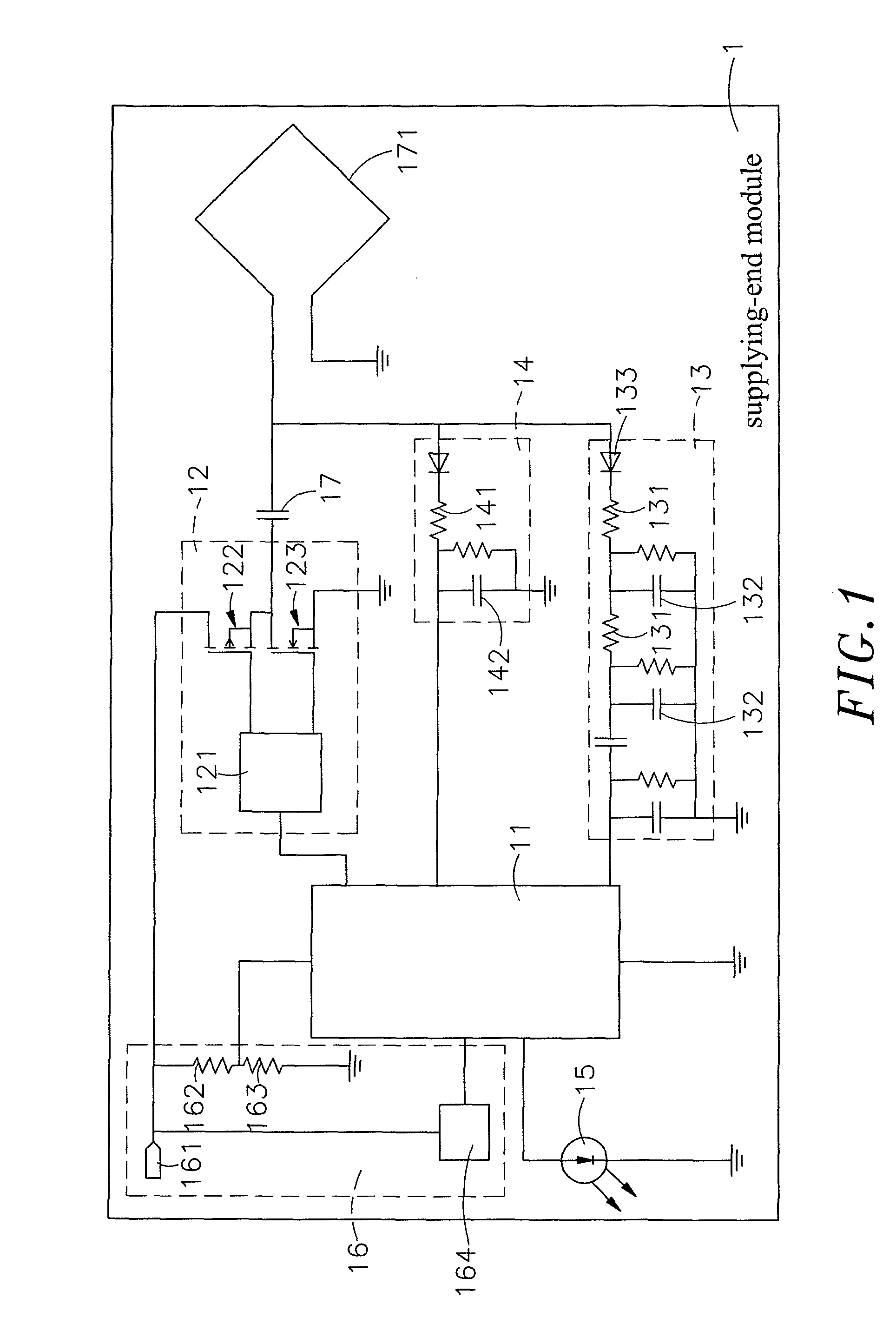
[0022]Referring to FIGS. 1 and 2, an induction type power supply system with synchronous rectification control for data transmission in accordance with the present invention is shown comprising a supplying-end module 1 and a receiving-end module 2.

[0023]The supplying-end module 1 comprises a supplying-end microprocessor 11 having installed therein operation / control / anti-noise data processing software programs, a power driver unit 12, a signal processing circuit 13, a coil voltage detection circuit 14, a display unit 15, a power supplying unit 16, a resonant capacitor 17 and a supplying-end coil 171. The power driver unit 12, the signal processing circuit 13, the coil voltage detection circuit 14, the display unit 15 and the power supplying unit 16 are respectively electrically coupled to the supplying-end microprocessor 11. The power driver unit 12 comprises a MOSFET (Metal-Oxide-Semiconductor Field-Effect Transistor) driver 121, a high-end MOSFET component 122 and a low-end MOSFET ...


PUM

PropertyMeasurementUnit
voltageaaaaaaaaaa
power lossaaaaaaaaaa
poweraaaaaaaaaa

Abstract

An induction type power supply system with synchronous rectification control for data transmission is disclosed to include a supplying-end module with a supplying-end coil and a receiving-end module with a receiving-end coil for receiving power supply from the supplying-end coil and providing a feedback data signal to the supplying-end coil during power supply transmission subject to the operation of a rectifier and signal feedback circuit of the receiving-end module that breaks off electric current transiently to change the load characteristics of the receiving-end coil, assuring a high level of data signal transmission stability and a high level of power transmission efficiency.

Description

BACKGROUND OF THE INVENTION[0001]1. Field of the Invention[0002]The present invention relates to power supply systems and more particularly, to an induction type power supply system with synchronous rectification control for data transmission, which comprises a supplying-end module, and a receiving-end module, which receives power supply from the supplying-end coil and provides a feedback data signal to the supplying-end coil during power supply transmission subject to the operation of a rectifier and signal feedback circuit of the receiving-end module that breaks off electric current transiently to change the load characteristics of the receiving-end coil of the receiving-end module, allowing transmission of the feedback data signal without causing power loss.[0003]2. Description of the Related Art[0004]In an induction type power supply system, the most important technique is to identify the object on the supplying-end coil. The power transmitting operation of the supplying-end of ...

Claims


Application Information

Patent Timeline
Patent Type & Authority Patents(United States)
IPC IPC(8): H01F27/42H01F37/00H01F38/00G06F1/26H02J5/00H02M3/335H04B5/00
CPCG06F1/26G06F1/266H02J5/005H02M3/33576H04B5/0037H04B5/0081H02J50/80H02J50/12H02M7/4815H02M3/33571Y02B70/10
Inventor TSAI, MING-CHIUCHAN, CHI-CHE
Owner FU TONG TECH
Learn More