
Method and apparatus for combusting syngas within a combustor

a combustor and syngas technology, applied in the field of combustor, can solve the problems of low heating value of syngas, flashback of conventional premixed dln combustion system, and highly reactive fuel stream with a very small characteristic chemical tim

Active Publication Date: 2015-07-14
GENERAL ELECTRIC CO
View PDF24 Cites 23 Cited by
  • Summary
  • Abstract
  • Description
  • Claims
  • Application Information

AI Technical Summary

Benefits of technology

This patent describes a method for operating a combustor by using two different gaseous fuels. The first gaseous fuel has a higher modifier index but lower reactivity, while the second gaseous fuel has a lower modifier index but higher reactivity. These two fuels are blended together to form a blended fuel, which is then injected into the combustor. This results in a more efficient combustion process with reduced emissions of nitrogen oxides (NOx). The patent also describes a dry low NOx combustor system that includes a blending device for blending the two fuels and an injection device for injecting the blended fuel into the combustor. This system can improve combustion efficiency and reduce NOx emissions in industrial applications.

Problems solved by technology

However, some known syngases have a low heating value as compared to other fuels, such as, natural gas, and, as such, may also have a low Modified Wobbe Index (MWI) as compared to other fuels.
Additionally, some known syngases have a significant hydrogen content, based on molar fuel fractions, that can result in a highly reactive fuel stream with a very small characteristic chemical time.
Due to this combination of low MWI and high fuel reactivity, conventional premixed DLN combustion systems can experience flashback when combusting syngas.
Over time, occurrences of flashback may be damaging to hardware within the combustor.
However, the proximity of the nitrogen supply to the combustion system and the additional compression the nitrogen may require before injection may add complexity and / or cost to the combustion systems, as compared to systems that do not include nitrogen injection into the combustor.
Ultimately, water availability and water quality may adversely affect such systems, and, as such, combustors using steam injection may require costly and complex steam systems to avoid the adverse effects of the water.

Method used


Image

  • Method and apparatus for combusting syngas within a combustor
  • Method and apparatus for combusting syngas within a combustor
  • Method and apparatus for combusting syngas within a combustor

Examples


Embodiment Construction

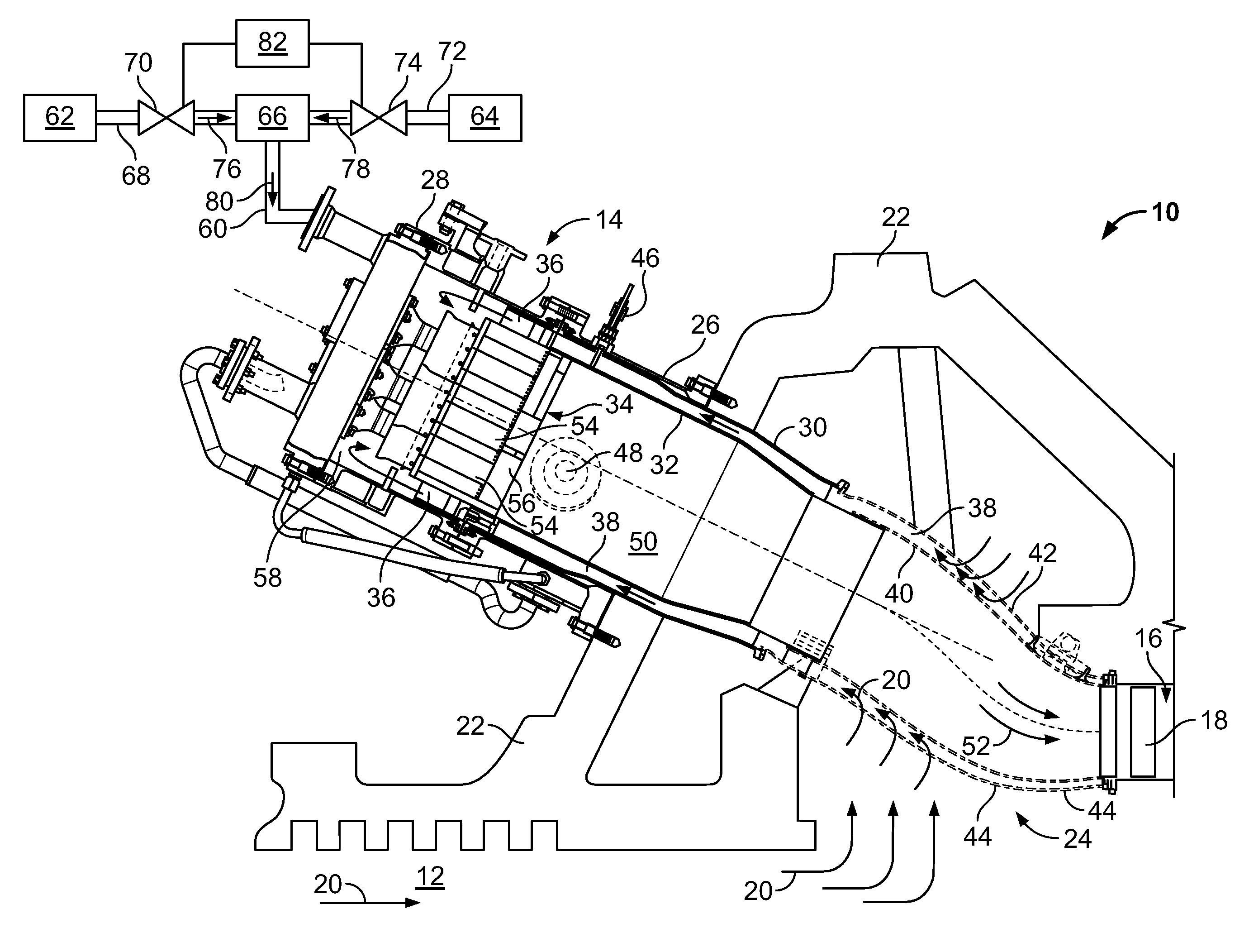
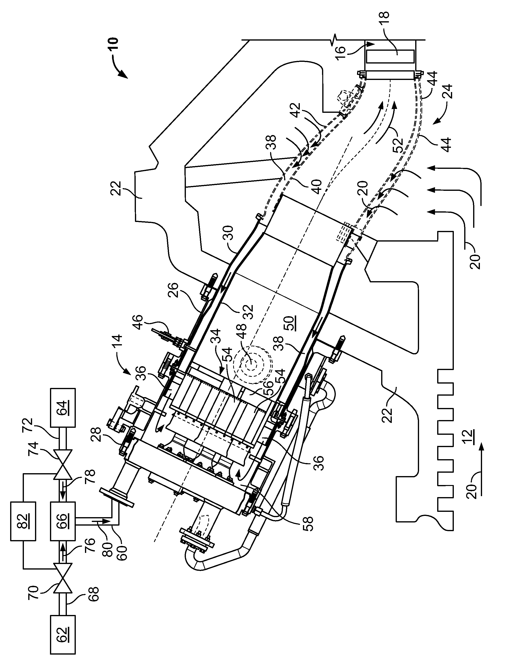
[0009]FIG. 1 is partial schematic side view of an exemplary gas turbine engine 10. Gas turbine engine 10 includes a compressor 12, a dry-low NOx combustor 14, and a turbine 16. Only a first stage nozzle 18 of turbine 16 is shown in FIG. 1. In the exemplary embodiment, turbine 16 is rotably coupled to compressor 12 with rotors (not shown) that are coupled to a single common shaft (not shown). Compressor 12 pressurizes inlet air 20 that is then channeled to combustor 14 for cooling combustor 14 and to provide air for the combustion process. More specifically, air 20 channeled to combustor 14 flows in a direction that is generally opposite to the flow of air through engine 10. In the exemplary embodiment, gas turbine engine 10 includes a plurality of combustors 14 that are oriented circumferentially about engine casing 22. More specifically, in the exemplary embodiment, combustors 14 are, for example, but are not limited to being, can-annular combustors.

[0010]In the exemplary embodimen...


PUM


Abstract

A method for operating a combustor is provided. The method includes supplying a predetermined amount of a first gaseous fuel to the combustor, wherein the first gaseous fuel has a first Modified Wobbe Index (MWI) and a first fuel reactivity, and supplying a predetermined amount of a second gaseous fuel to the combustor, wherein the second gaseous fuel has a second MWI that is lower than the first MWI and a second fuel reactivity that is higher than the first fuel reactivity. The method also includes mixing the first and second gaseous fuels together to form a blended gaseous fuel, and injecting the blended gaseous fuel into the combustor.

Description

BACKGROUND OF THE INVENTION[0001]This invention relates generally to a combustor, and, more specifically, to a dry-low nitrogen oxide (NOx) (DLN) combustion system for a gas turbine engine.[0002]Combustion systems of at least some known gas turbine engines combust synthesis gas, or syngas, to create exhaust gases that drive a gas turbine. However, some known syngases have a low heating value as compared to other fuels, such as, natural gas, and, as such, may also have a low Modified Wobbe Index (MWI) as compared to other fuels. Additionally, some known syngases have a significant hydrogen content, based on molar fuel fractions, that can result in a highly reactive fuel stream with a very small characteristic chemical time. Due to this combination of low MWI and high fuel reactivity, conventional premixed DLN combustion systems can experience flashback when combusting syngas. “Flashback” refers to a condition that may occur when the aerodynamics of fuel introduction and mixing are ov...

Claims


Application Information

Patent Timeline
Patent Type & Authority Patents(United States)
IPC IPC(8): F02C3/20F02C1/00F02C3/22F02C9/40F23R3/36
CPCF02C3/22F02C9/40F23R3/36F23N2037/08F23N2041/20F23N2237/08F23N2241/20
Inventor ZIMINSKY, WILLY STEVEKRAEMER, GILBERT OTTOYILMAZ, ERTAN
Owner GENERAL ELECTRIC CO
Learn More