Energy chassis and energy exchange device

a technology of energy chassis and energy exchange device, which is applied in the direction of ac network voltage adjustment, heat storage plant, special data processing applications, etc., to achieve the effect of simplifying the design and construction of the building energy system, efficient meeting building energy requirements, and increasing the efficiency of building heating and cooling systems

Active Publication Date: 2015-07-14
GREENSLEEVES TECH CORP
View PDF51 Cites 44 Cited by
  • Summary
  • Abstract
  • Description
  • Claims
  • Application Information

AI Technical Summary

Benefits of technology

[0026]A primary objective of the present invention is to provide systems, methods and devices for a simple to implement, multifunctional, factory produced, self-contained (aside from sources / sinks / storage and piping), fully integrated, automated heating and cooling system that incorporates methods and devices required for a building HVAC system that includes, but is not limited to, automated real time and future energy requirement projections for a building, or group of buildings, to more efficiently meet building energy requirements. This energy management capability uses devices having the automated functionality of energy sensing, load forecasting, harvesting, storage, management and transportation to increase the efficiency of building heating and cooling systems while simplifying the design and construction of the building energy system. This system requires much less custom engineering, less on-site construction time and complexity than currently available alternatives.
[0028]A third objective of the present invention is to provide systems, methods and devices to efficiently transport energy from where it is produced where it is needed without introducing a lot of complexity to the construction process. This includes set up screens for the system that allow it to be easily customized to the implementation.
[0029]A fourth objective of the present invention is to provide systems, methods and devices for a mechanical-controlled and computer-controlled fluid mix determination and temperature-control systems and interconnectivity functionality including methods and devices for controlling the transportation and exchange of energy. This functionality facilitates the selection, interconnection and switching required for the mixing and use of common and uncommon sources of energy, so as to use that energy more efficiently. Said functionality also facilitates the selection, switching, and interconnection of the common and uncommon devices including solar collectors, geothermal, energy recovery units, fuel cells and other sources of energy required to use said sources and to allow the sources to be mixed to increase the efficiency of the energy harvesting, to use multiple inputs connected to multiple outputs, and to provide significant increase in energy synergy.
[0030]A fifth objective of the present invention is to provide fully integrated and automated systems, methods and devices for providing a next generation geothermal heat exchanger that employs the ability to mix different types of loops in a single implementation, to charge some of the loops with thermal energy while others are being simultaneously discharged and to store energy in the loops and that incorporates the intelligence and controls of the system into a standardized product that can be attached to any form of closed loop geothermal heat pump system. This geothermal heat exchanger can be used as an optional addition to the energy chassis device (i.e. the complete central heating, cooling and energy management system that includes the computer, software, refrigerant-based heat transfer device such as a heat pump, circulating pumps and variable speed drives, interconnecting piping, sensors and control devices, plus the electrical connections, inverters, switches, fuses and wiring and the like required to manage and control the electrical and HVAC system), or in a stand-alone configuration to significantly reduce the custom engineering, construction time and construction complexity required to implement a geothermal system with equivalent functionality.
[0031]A sixth objective of the present invention is to provide systems, methods and devices for providing a next generation geothermal heat exchanger that uses emerging computer technology, sensor and control technology, advanced heating and cooling concepts, and the ability to package the intelligence and control platform into a standardized product for a combination and integration of technology that increases the performance of the geothermal system while maintaining, or reducing, the installed cost of the system.
[0033]An eighth objective of the present invention is to provide systems, methods, and devices for managed and measured short and long-term thermal energy storage in a hybrid configuration (i.e. the combination of multiple types of sources / sinks in the same system), utilizing various forms of geothermal heat exchanger configurations in addition to energy storage within the building fabric (structure) via embedded hydronic piping that can also be combined with other thermal storage such as phase change materials / ice storage, chilled water storage, phase change materials / hot water storage, etc. The invention allows for integration with all thermal energy storage known in the art, as well as any future energy storage. The use of thermal energy storage time shifts energy harvested from the environment, so it can be used when the original source is not available (e.g. the sun is down, waste heat is not being produced, people have left the building, and the like). This allows multiple sources of energy to be merged so that when one source is insufficient, or too expensive to implement to meet the full load requirement, multiple sources can be used to reduce the amount of capital required to build the entire system that makes each source available in a reservoir, so that it may be reliably used according to projected system needs and optimization calculations.

Problems solved by technology

Energy consumption in commercial buildings is a very expensive component of the cost for operating and maintaining a building.
For example, commercial buildings have expensive air conditioning and heating needs which over the lifetime of the building often add up to more than double the first cost for construction.
Attempts over the years to reduce energy consumption have resulted in adding substantial increases in construction costs which are not recouped over the short term.
The typical commercial building heating and cooling system used in the U.S. today is a Variable Air Volume (VAV) system, typically configured this system cannot utilize sustainable energy sources.
Buildings represent 40% of the energy used in the U.S. and are fueled almost entirely with fossil fuels that are expensive and damaging to the environment.
There are a number of problems that make these HVAC systems energy inefficient, unhealthy, uncomfortable, and that create barriers to adopting new technologies.
These problems include:Pressure on construction costs encourages owners to keep up front costs low by purchasing inexpensive, wasteful HVAC systemsWasting excess energy rejected through chillers, etc. rather than moving it to where it is needed or storing it for later useHigh energy movement through walls because of inadequate insulation—in conventional systems the shell is not part of the solution, but in the invention it can be made to be an energy storage deviceConstantly reheating and re-cooling the building mass rather than holding it at temperatureOverbuilt, inefficient systems that could be made much smallerThe inability to use local energy (e.g. solar, body heat, etc.)Heating the building when the heating system is least efficient and likewise cooling the building when the cooling system is least efficient—with energy storage, this can be reversed to increase efficiencyGeothermal systems are typically more costly to build and their function is not designed to maximize efficiency which in turn reduces the use of these systems
The rapidly changing alternative energy technologies that are being developed are created in silos to perform the functions of that technology and do not work together without custom integration.
These often prove to be unreliable or fail.
Few engineering firms have the resources to research and integrate innovative solutions and as a result do not commonly design them into client buildings.
The custom-build process is very expensive and limits market use while the standardized product brings down costs and expands the market.
While we are aware that there is a great deal of energy available locally (e.g. body heat, lighting heat, computer heat, solar thermal, solar photovoltaic, geothermal, etc.) the U.S. has failed to adopt a significant use of local energy harvesting (i.e. alternative or renewable energy).
Current geothermal heat exchanger design is not optimized to provide cooler water to support sensible cooling devices such as radiant cooling panels and chilled beams.
Instead, they mix higher and lower temperature water together which reduces the ability to provide sensible cooling with these devices.
Additionally, current geothermal heat exchanger design is not configured to maximize the ability to store energy for later use by mixing / combining various heat exchanger configurations.
This method does not allow for loops to be separated for different uses; it combines all inputs and all outputs into a two pipe (one in, one out) system.
As it does not combine these inputs, it cannot reach the most efficient energy use solution.

Method used


Image

  • Energy chassis and energy exchange device
  • Energy chassis and energy exchange device
  • Energy chassis and energy exchange device

Examples


Embodiment Construction

[0058]Before explaining the disclosed embodiments of the present invention in detail it is to be understood that the invention is not limited in its application to the details of the particular arrangements shown since the invention is capable of other embodiments. Also, the terminology used herein is for the purpose of description and not of limitation.

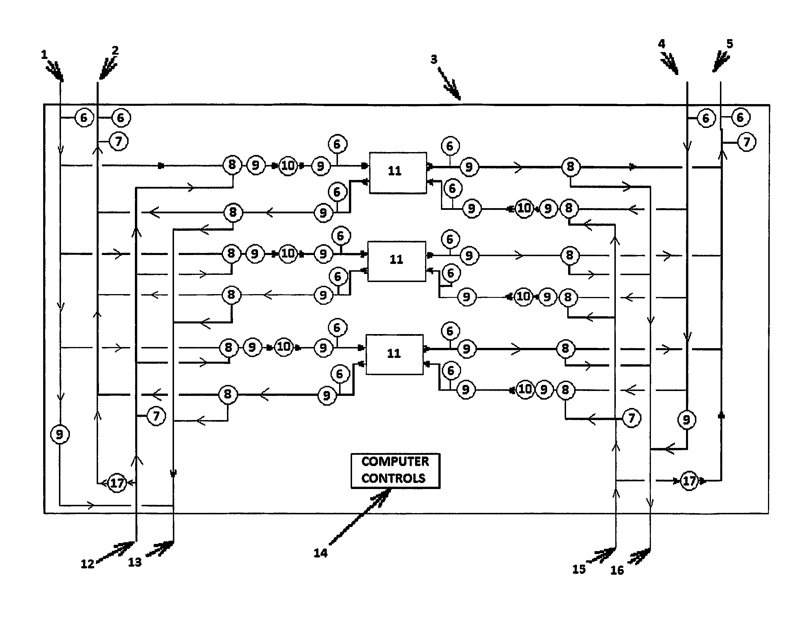
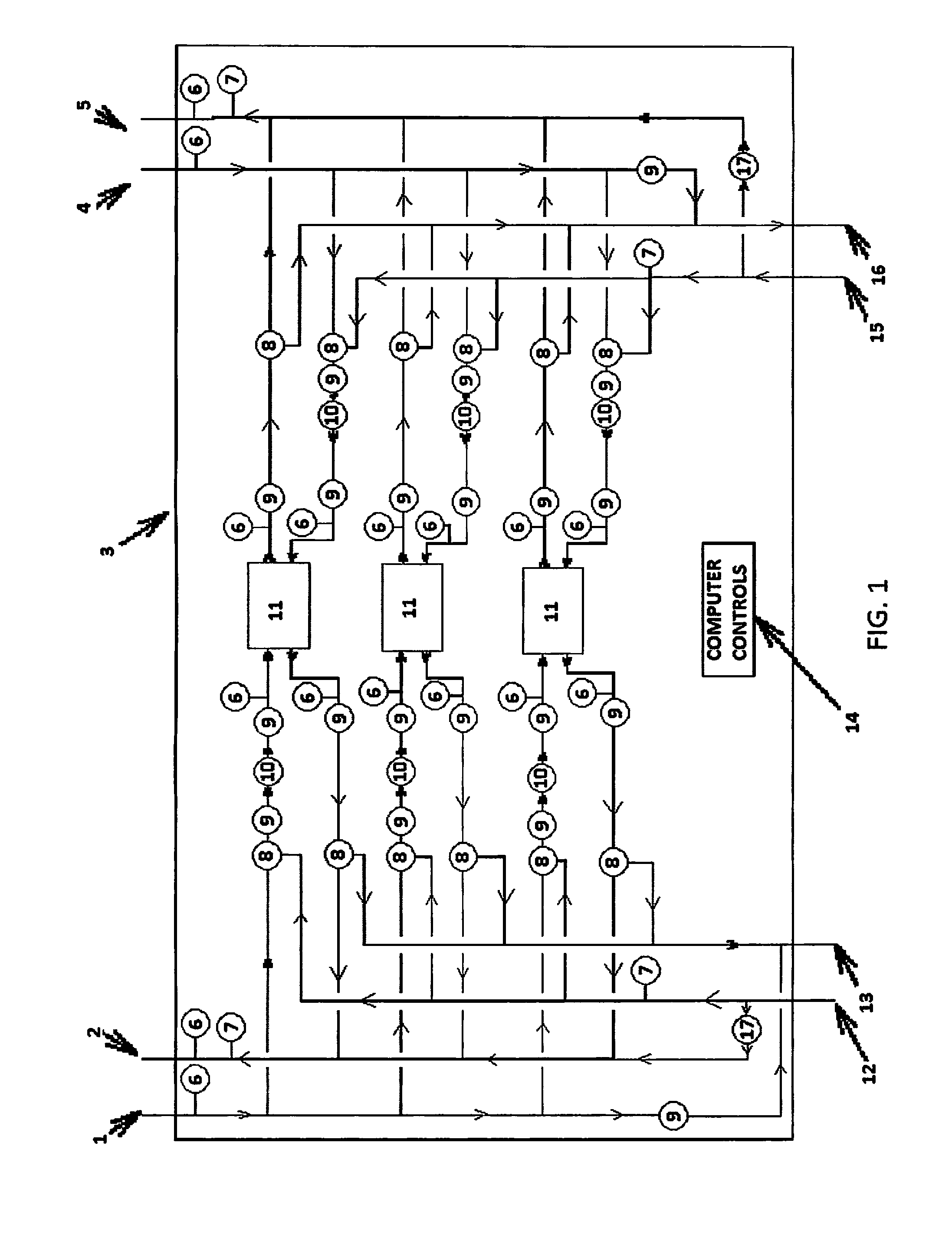
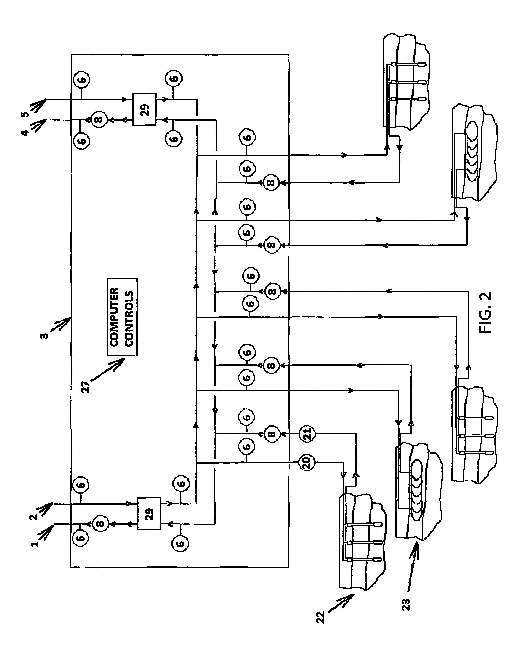
[0059]The following is a list of reference numerals used in the description and the drawings to identify components:

[0060]

17 variable volume circulation14 computer-based control systempump15 supply connection from “cool”20 geothermal earth heat exchangerside of energy exchange devicereturn16 return connection to “cool” side21 geothermal earth heat exchangerof energy exchange devicesupply27 exchange computer22 Vertical closed loop geothermal23 horizontal, “Slinky” closed loopheat exchangegeothermal heat exchanger1 hot fluid return29 heat exchanger2 hot fluid source31 energy sys management3 energy chassiscomputer4 cold fluid return32 r...


PUM


Abstract

Systems, methods and devices for utilizing an energy chassis device designed to sense, collect, store and distribute energy from where it is available using devices that harvest or convert energy to locations requiring energy such as but not limited to HVAC (heating, ventilation and cooling) systems. The systems, methods and devices can also be used with a next generation geothermal heat exchanger that achieves higher energy harvesting efficiency and provides greater functionality than current geothermal exchangers.

Description

[0001]This application claims the benefit of priority to U.S. Provisional Application No. 61 / 331,525 filed on May 5, 2010.FIELD OF THE INVENTION[0002]This invention relates to building, heating and cooling systems (HVAC) systems and electrical systems, in particular to systems, methods, and devices used to sense and collect local sources of naturally renewable energy, to store energy and to redistribute energy to efficiently meet building needs by using a fully integrated, factory assembled device.BACKGROUND AND PRIOR ARTEnergy Consumption Costs and Problems[0003]Energy consumption in commercial buildings is a very expensive component of the cost for operating and maintaining a building. For example, commercial buildings have expensive air conditioning and heating needs which over the lifetime of the building often add up to more than double the first cost for construction. Attempts over the years to reduce energy consumption have resulted in adding substantial increases in construc...

Claims


Application Information

Patent Timeline
Patent Type & Authority Patents(United States)
IPC IPC(8): G06F19/00F24D19/10F28D20/00H02J3/14F24J3/08F24D12/02G06Q10/04G06Q50/06F24F5/00F24F11/00
CPCF24J3/081F24D12/02F24D19/1048F28D20/00G06Q10/04G06Q50/06H02J3/14F24D2200/11F24D2200/12F24D2200/22F24F2005/0057F24F2011/0075F24J2200/06F28F2200/00Y02B10/40Y02B10/70Y02B30/14Y02B30/52Y02B30/762Y02B70/3225Y02B70/3275Y02E10/12Y02E60/142Y02E70/30Y04S20/222Y04S20/244F24F11/46F24T10/10F24T2010/56F24T2201/00H02J2310/12H02J2310/14F24T10/00Y02B30/00Y02B30/70Y02B70/30Y02E10/10Y04S20/242Y02E60/14
Inventor HAMSTRA, STEPHEN A.LINN, W. MICHAEL
Owner GREENSLEEVES TECH CORP
Why Eureka
Try Eureka