Determining a flow characteristic of an object being movable in an element

a technology of moving objects and flow characteristics, applied in the field of sensor devices, can solve the problems of poor low accuracy of blood flow characteristic determination based on smi, and achieve the effect of accurately and easily determining the flow characteristi

Active Publication Date: 2015-07-28
KONINK PHILIPS ELECTRONICS NV
View PDF13 Cites 12 Cited by
  • Summary
  • Abstract
  • Description
  • Claims
  • Application Information

AI Technical Summary

Benefits of technology

[0011]It is an object of the present invention to provide a method for accurately and easily determining a flow characteristic of an object being movable in an element. Further, it is an object of the invention to provide a sensor device allowing for accurately and easily determining the flow characteristic of the object being movable in the element.

Problems solved by technology

Thus, the above described measurement technique may comprise low depth sensitivity, and, when considering a small Doppler frequency shift, an accuracy of the determination of the flow characteristic of the blood may be low.
As stated above, the determination of the flow characteristic of the blood based on SMI may also suffer from a poor accuracy.

Method used


Image

  • Determining a flow characteristic of an object being movable in an element
  • Determining a flow characteristic of an object being movable in an element
  • Determining a flow characteristic of an object being movable in an element

Examples


Embodiment Construction

[0050]The invention in the drawing is schematic. It is noted that in different Figures, similar or identical elements are provided with the same reference signs or with reference signs, which are different from the respective reference signs only within a first digit.

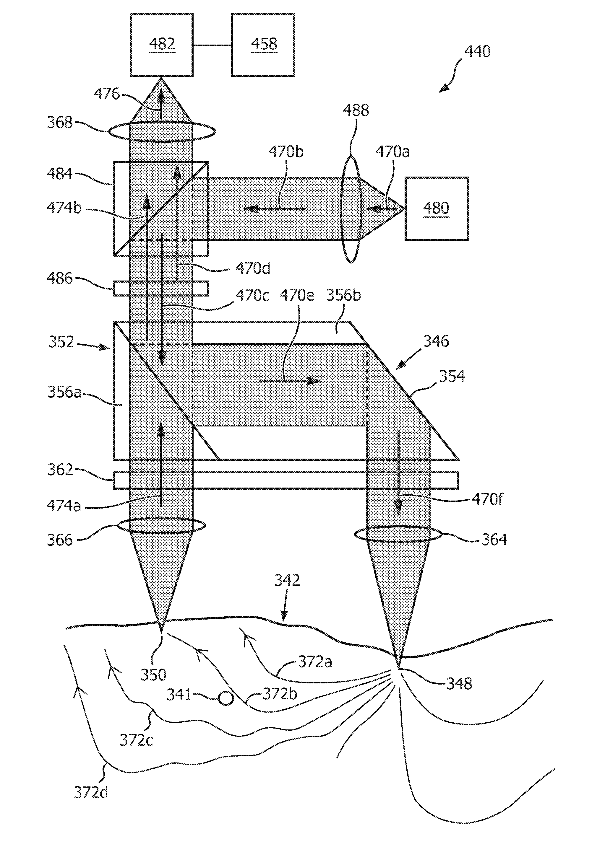
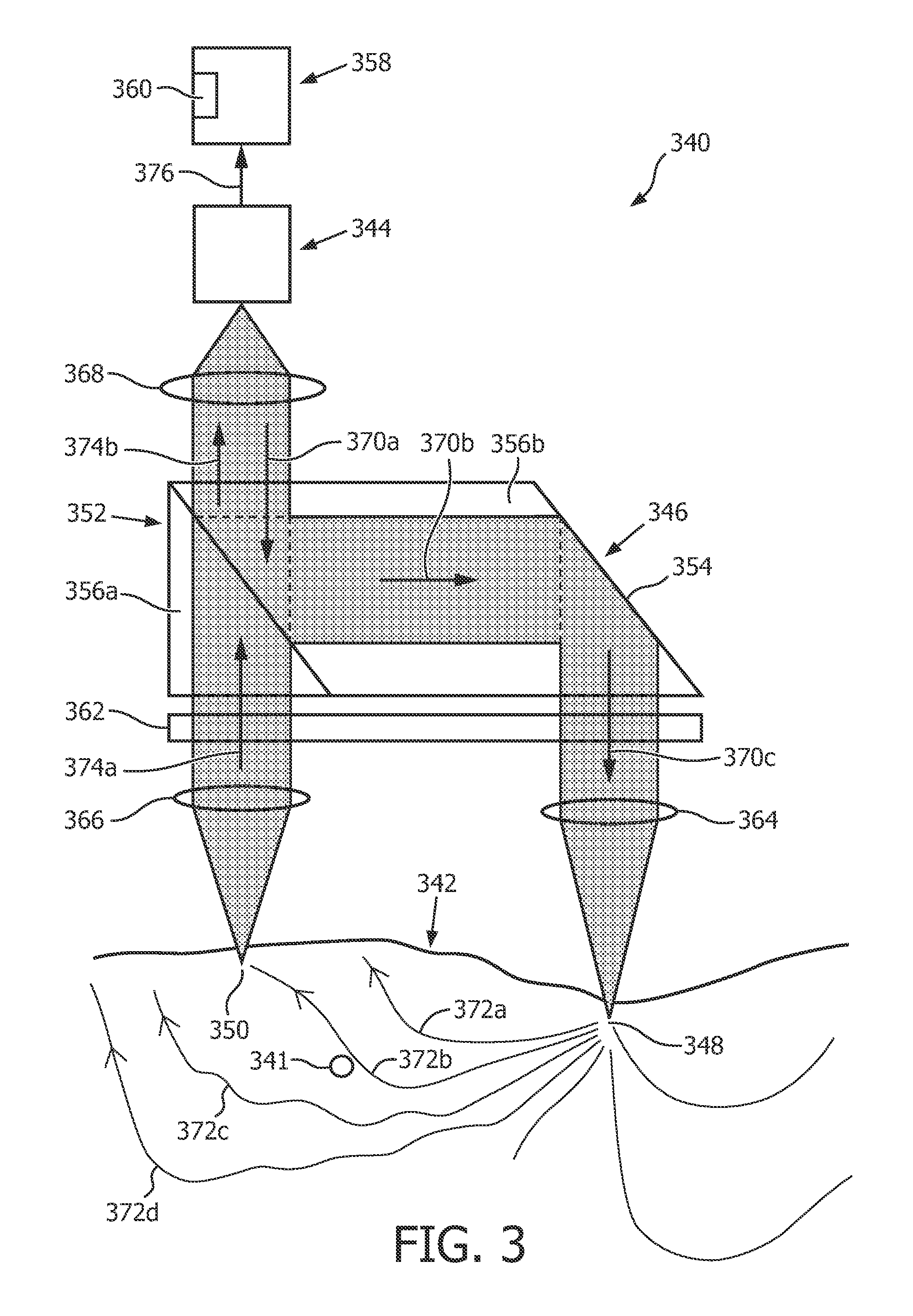
[0051]Referring to FIG. 3, a SMI based sensor device 340 for determining a flow characteristic of an object being movable in an element according to a first exemplary embodiment of the invention is illustrated. The sensor device 340 is used in the medical area for monitoring blood perfusion of a person by determining a flow velocity of blood cells 341 in a skin 342 of the person. For illustration purposes, a single blood cell 371 is schematically illustrated in FIG. 3. The sensor device 340 comprises an improved depth sensitivity and thus and an improved signal-to-noise ratio, since the sensor device 340 is sensitive to deeper layers of the skin 342 to be investigated.

[0052]The sensor device 340 comprises a light emitti...


PUM

PropertyMeasurementUnit
angleaaaaaaaaaa
infrared wavelengthsaaaaaaaaaa

Abstract

A sensor device (340) for determining a flow characteristic of an object (341) being movable in an element (342) comprises a light emitting unit (344) configured for emitting light towards the element (342) and a light detecting unit (344) configured for detecting light scattered back from the element (342). The sensor device (340) comprises an optical unit (346) configured for spatially separating a light incidence element portion (348) of the element (342) and a light detection element portion (350) of the element (342) from one another, wherein the light incidence element portion (348) is associated with the emitted light inciding on the element (342) and the light detection element portion (350) is associated with the back-scattered light scattered back from the element (342) for detection. The sensor device (340) comprises a determining unit (358) configured for determining the flow characteristic of the object (341) being movable in the element (342) based on light indicative of the emitted light and the detected back-scattered light. The sensor device (340) allows for an accurate and easy determination of the flow characteristic of the object (341).

Description

FIELD OF THE INVENTION[0001]The invention relates to a sensor device for and a method of determining a flow characteristic of an object being movable in an element.BACKGROUND OF THE INVENTION[0002]Laser Doppler velocimetry (LDV), which is also referred to by laser Doppler anemometry (LDA) represents a measurement technique for determining a flow characteristics of a movable object using the Doppler effect. In particular, Laser Doppler velocimetry is usable in conjunction with medical diagnosis applications, in order to, for example, determine a flow characteristic of micro vascular blood or tissue perfusion characteristics of a person. In the medical area, LDV is also referred to as laser Doppler flowmetry (LDF). Alternatively, the technique may be used in the area of material machining, in order to determine a flow characteristic of a material particle stream. In the following, reference is made to the medical area without loss of generality.[0003]One LDF based technique for determ...

Claims


Application Information

Patent Timeline
Patent Type & Authority Patents(United States)
IPC IPC(8): G01N21/00G01S17/58G01P5/26G01P3/36A61B5/00G01F1/00A61B5/026G01N21/53G01S7/491G01S17/88
CPCG01F1/00A61B5/0261A61B5/6801G01N21/53G01P3/366G01P5/26G01S7/4916G01S7/4917G01S17/58G01S17/88A61B2562/0233A61B2562/146
Inventor VAN DER LEE, ALEXANDER MARCVEEN, JEROEN
Owner KONINK PHILIPS ELECTRONICS NV
Why Eureka
Try Eureka