
Tunneling magnetoresistive (TMR) device with MgO tunneling barrier layer and nitrogen-containing layer for minimization of boron diffusion

a tunneling barrier and tunneling layer technology, applied in the field of tunneling magnetoresistance (tmr) devices, can solve the problems of low magnetoresistance, undesirable increase in interlayer coupling field (hsub>int), and degrade the performance of the tmr read head

Active Publication Date: 2015-08-04
WESTERN DIGITAL TECH INC
View PDF7 Cites 25 Cited by
  • Summary
  • Abstract
  • Description
  • Claims
  • Application Information

AI Technical Summary

Benefits of technology

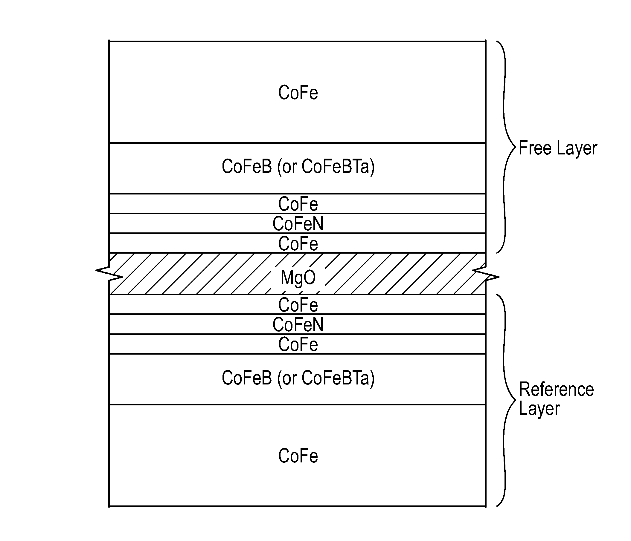
The invention is related to a device called TMR (tunnelling magnetoresistive) that includes a thin layer of MgO and a nitrogen-containing layer between the MgO barrier layer and the free (unencapsulated) or reference ferromagnetic layers. The use of a thin MgO barrier layer leads to higher values of TMR (the ratio of tunnelling current to magnetic field) and lower values of interlayer coupling field (Hint) than devices without the nitrogen-containing layers. The patent text describes the technical effects of this invention and how it can improve the performance of TMR devices.

Problems solved by technology

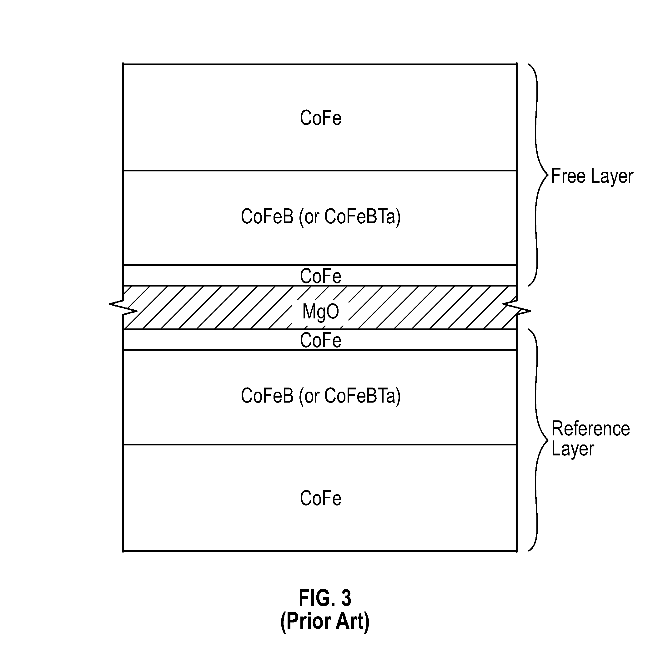
For CoFe / MgO / CoFe tunnel junctions it is known that magnetoresistance is low due to inferior crystallinity of the MgO barrier layer.
The reduction in MgO thickness also results in an undesirable increase in interlayer coupling field (Hint), i.e., the strength of the magnetic coupling field between the reference layer and the free layer.
A large Hint degrades the performance of the TMR read head.

Method used


Image

  • Tunneling magnetoresistive (TMR) device with MgO tunneling barrier layer and nitrogen-containing layer for minimization of boron diffusion
  • Tunneling magnetoresistive (TMR) device with MgO tunneling barrier layer and nitrogen-containing layer for minimization of boron diffusion
  • Tunneling magnetoresistive (TMR) device with MgO tunneling barrier layer and nitrogen-containing layer for minimization of boron diffusion

Examples


Embodiment Construction

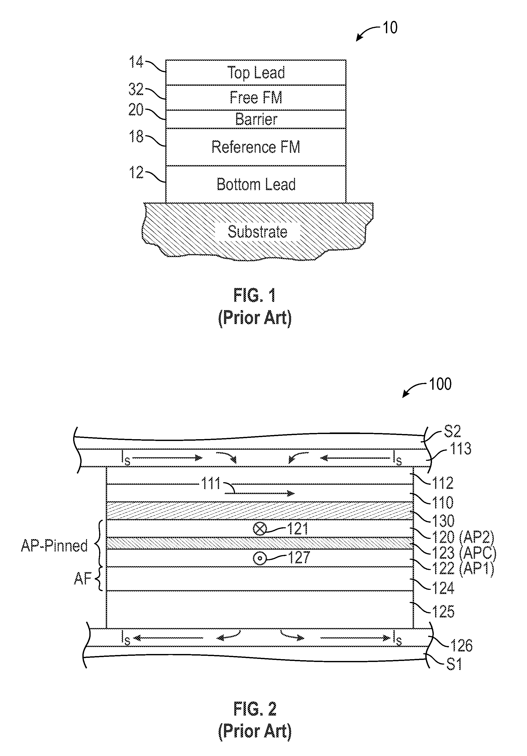
[0017]FIG. 2 is a cross-sectional highly schematic view illustrating the structure of a prior-art TMR read head 100 like that used in a magnetic recording disk drive. This cross-sectional view is a view of what is commonly referred to as the air-bearing surface (ABS) of the TMR read head 100. The TMR read head 100 includes a sensor stack of layers formed between two ferromagnetic shield layers S1, S2 that are typically made of electroplated NiFe alloy films. The lower shield S1 is typically smoothened by chemical-mechanical polishing (CMP) to provide a smooth surface for the growth of the sensor stack. The sensor stack includes a ferromagnetic reference layer 120 having a pinned magnetization 121 oriented transversely (away from the page), a ferromagnetic free layer 110 having a magnetization 111 that can rotate in the plane of layer 110 in response to transverse external magnetic fields from a recording disk, and an electrically insulating tunneling barrier layer 130, typically mag...


PUM


Abstract

A tunneling magnetoresistance (TMR) device, like a magnetic recording disk drive read head, has a nitrogen-containing layer between the MgO barrier layer and the free and / or reference ferromagnetic layers that contain boron. In one embodiment the free ferromagnetic layer includes a boron-containing layer and a trilayer nanolayer structure between the MgO barrier layer and the boron-containing layer. The trilayer nanolayer structure includes a thin Co, Fe or CoFe first nanolayer in contact with the MgO layer, a thin FeN or CoFeN second nanolayer on the first nanolayer and a thin Co, Fe or CoFe third nanolayer on the FeN or CoFeN nanolayer between the FeN or CoFeN nanolayer and the boron-containing layer. If the reference ferromagnetic layer also includes a boron-containing layer then a similar trilayer nanolayer structure may be located between the boron-containing layer and the MgO barrier layer.

Description

BACKGROUND OF THE INVENTION[0001]1. Field of the Invention[0002]The invention relates generally to tunneling magnetoresistance (TMR) devices, and more particularly to a TMR read head with a magnesium oxide (MgO) tunneling barrier layer and a boron-containing ferromagnetic layer.[0003]2. Description of the Related Art[0004]A tunneling magnetoresistance (TMR) device, also called a magnetic tunneling junction (MTJ) device, is comprised of two ferromagnetic layers separated by a thin insulating tunneling barrier layer. The barrier layer is typically made of a metallic oxide that is so sufficiently thin that quantum-mechanical tunneling of charge carriers occurs between the two ferromagnetic layers. While various metallic oxides, such as alumina (Al2O3) and titanium oxide (TiO2), have been proposed as the tunneling barrier material, the most promising material is crystalline magnesium oxide (MgO). The quantum-mechanical tunneling process is electron spin dependent, which means that an el...

Claims


Application Information

Patent Timeline
IPC IPC(8): G11B5/39
CPCG11B5/3909G11B5/39G01R33/093G01R33/098
Inventor FREITAG, JAMES MACGAO, ZHENG
Owner WESTERN DIGITAL TECH INC
Learn More