Continuous collection method of particle component in aqueous solution and apparatus therefor

a technology of continuous particle component and aqueous solution, which is applied in the direction of solvent extraction, separation process, filtration treatment, etc., can solve the problems of increased running cost, increased maintenance cost, and difficult handling, and achieves more stable operation, finer grain, and stable operation

Active Publication Date: 2015-08-18
JAPAN ATOMIC ENERGY AGENCY INDEPENDANT ADMINISTRATIVE CORP
View PDF11 Cites 0 Cited by
  • Summary
  • Abstract
  • Description
  • Claims
  • Application Information

AI Technical Summary

Benefits of technology

The present invention provides a counter-current type emulsion flow continuous liquid-liquid extraction apparatus that can generate high quality emulsion flow, scale up the apparatus, prevent the particle component in the aqueous solution from plugging holes in the head part, and enable the simultaneous collection of dissolved and particle components as necessary. The apparatus and method are advantageous in that they have the same features as the conventional column-type liquid-solid extraction method and can attain high quality and stable emulsion flow. The apparatus and method can be used in various industrial fields and overcome the plugging problem in the head part that was identified as a critical weak point of the emulsion flow apparatus based on the single current method.

Problems solved by technology

The above mentioned apparatuses, however, have the common principle for mixing two liquid phases by applying mechanical external forces (such as stirring and vibrating) continuously or intermittently, which may lead to such disadvantageous aspects as being not easy to handle, increased running cost, increased maintenance cost, increased apparatus manufacturing cost (initial cost), uncertain safety features.
More specifically, they include: 1) large energy load required to generate mechanical external forces; 2) load and stress at the driving parts for generating mechanical external forces; 3) long adjusting work required to prepare and setup the operation of apparatus; 4) risk of ignition due to friction or static electricity at the driving parts; 5) high strength and high price materials required to manufacture the driving parts; 6) ambient noises in connection with stirring, vibrating and high-speed rotating operations; and 7) uncertainty in ensuring safety during earthquake.
Although emulsion flow technology is an innovative method as described above, it has some unresolved problems.
At first, in the conventional single current method, it is difficult to generate fine-grained and high quality emulsion flow, and it is not easy to obtain the extraction rate (extractability) over 90% because some amount of non-uniformity occurs.
In addition, in the single current method, as it is difficult to maintain stable emulsion flow in the wide region, there is a problem in scale-up of the apparatus.
This plugging problem has been a major challenge in the improvement of the emulation flow because the particle component may typically coexist as suspension materials in the aqueous solution.

Method used


Image

  • Continuous collection method of particle component in aqueous solution and apparatus therefor
  • Continuous collection method of particle component in aqueous solution and apparatus therefor
  • Continuous collection method of particle component in aqueous solution and apparatus therefor

Examples


embodiment 1

Experiment for Collecting Particle Component in Aqueous Solution by Small-Sized Apparatus

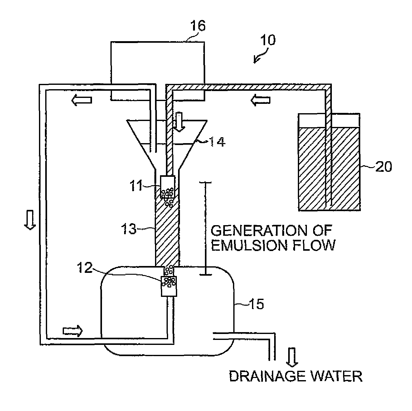
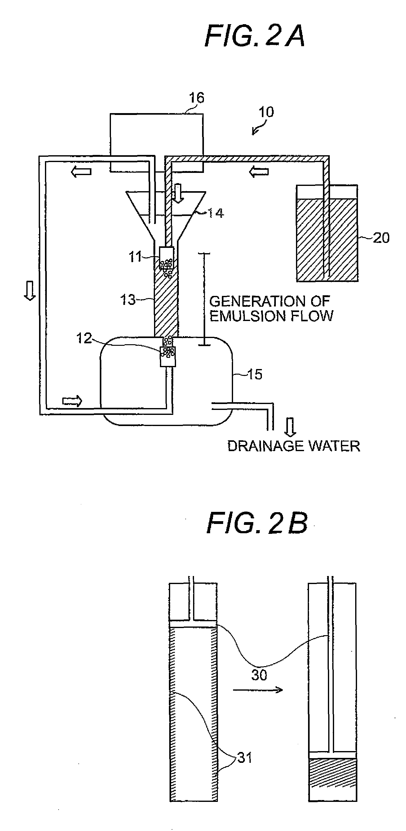
[0047]Refer to FIG. 3A and FIG. 3B. Using a small-sized emulsion flow apparatus 10a (with the apparatus volume=3 litters and the apparatus weight=2 kg), an experiment for collecting aluminum oxide Al2O3 particles was carried out. More specifically, 20 litters of aqueous nitric acid solution (pH 2) including aluminum oxide Al2O3 particles (with particle diameter between 20 μm and 25 μm) by 0.02 M were prepared and an experiment for collecting the particle component was carried out by using a small-sized emulsion flow apparatus provided with 1 litter of isooctane. FIG. 3A shows a photo picture of the small-sized emulsion flow apparatus used in the experiment. The first head part 11 used in the apparatus has such a structure that the side wall of the hollow cylinder with its one end being closed, being made of polypropylene, and being provided with 10 holes having 1 mm diameter. The second head par...

embodiment 2

Experiment for Collecting Particle Component in Aqueous Solution by Intermediate-Sized Apparatus

[0049]Refer to FIG. 4A. FIG. 4A shows an intermediate-sized emulsion flow apparatus. The term of “Intermediate-sized” apparatus means an apparatus having an apparatus volume three times larger than the apparatus volume used in Embodiment 1. In this experiment, the intermediate-sized emulsion flow apparatus shown in FIG. 4A (with the apparatus volume=9 litters and the apparatus weight=4 kg) was used. The first head part 11 used in the apparatus has such a structure that the side wall of the hollow cylinder with its one end being closed, being made of polypropylene, and being provided with 6 holes having 4.8 mm diameter. The second head part 12 has such a structure that a sintered glass plate having pores with 40 μm diameter bonded onto the end of the hollow cylinder as described above. In order to avoid emulsion mixed phase and supply clean solvent phase, the upper phase separation part 14...

embodiment 3

Experiment for Collecting Simultaneously Particle Component and Dissolved Component in Aqueous Solution

[0053]Dissolved metallic ion and suspended particle component can be selectively and simultaneously collected by adding an extraction agent relevant to the metal ion to such a solvent phase as isooctane; while, in Embodiment 1 and Embodiment 2, pure isooctane is used. In Embodiment 3, an experiment was carried out by using the above described intermediate-sized emulsion flow apparatus provided with 2 litters of isooctane including bis(2-ethylhexyl)phosphoric acid (DEHPA) as the extraction agent by 1×10⁻³ M and with 200 litters of aqueous nitric acid solution (pH 2) including aluminum oxide Al2O3 particles as the particle component by 0.02 M and ytterbium Yb (trivalent ion) as the dissolved component by 6×10⁻⁶ M. As the experimental result, almost 100% of aluminum oxide Al2O3 particles as the particle component and about 98% of ytterbium Yb as the dissolved component could be separa...


PUM

PropertyMeasurementUnit
extractabilityaaaaaaaaaa
heightaaaaaaaaaa
particle diameteraaaaaaaaaa

Abstract

The particle components may be collected by using a phenomenon that the particle components in the aqueous phase aggregate at the liquid-to-liquid interface. Both of the particle components and the dissolved components in the aqueous phase may be simultaneously collected if combined with liquid-liquid extraction phenomenon that the dissolved components in the aqueous phase are collected into the solvent phase through the liquid-to-liquid interface. The aggregation phenomenon of the particle components at the liquid-to-liquid interface may be promoted by using an emulsion flow method, a method of applying mechanical external forces (such as stirring and vibrating) or another method combining both the above-mentioned methods.

Description

CROSS-REFERENCE TO RELATED APPLICATION[0001]This application is a divisional application of U.S. application Ser. No. 12 / 570,470, filed Sep. 30, 2009, the contents of which are incorporated herein by reference.BACKGROUND OF THE INVENTION[0002]The present invention relates to a method for collecting continuously particle component in the aqueous solution without using filters and / or centrifuge separators. The method utilizes a phenomenon that particle component in the aqueous solution aggregates at the liquid-to-liquid interface between the aqueous solution (aqueous phase) containing the particle component as the target component and the solvent (solvent phase) having hydrophobic nature and not mixing with water.[0003]Liquid-liquid extraction method (solvent extraction method), by which the target component included in the aqueous solution may be extracted into the solvent (such as organic solvent) that contains extraction agents (extractants) having hydrophobic nature and does not m...

Claims


Application Information

Patent Timeline
Patent Type & Authority Patents(United States)
IPC IPC(8): B01D11/04C02F1/26C02F1/00C02F1/54
CPCB01D11/0434B01D11/0438C02F1/26C02F1/001C02F1/54
Inventor NAGANAWA, HIROCHIKAYANASE, NOBUYUKINAGANO, TETSUSHI
Owner JAPAN ATOMIC ENERGY AGENCY INDEPENDANT ADMINISTRATIVE CORP
Why Eureka
Try Eureka