
Method for producing a composite including a ceramic matrix

a ceramic matrix and composite material technology, applied in the direction of instruments, surveying and navigation, reactor fuel elements, etc., can solve the problems of low rigidity, difficult to use to form parts of long lengths but of small diameters such as tubes, and difficult to respect the dimensions and tolerances of parts over long lengths

Inactive Publication Date: 2015-09-29
COMMISSARIAT A LENERGIE ATOMIQUE ET AUX ENERGIES ALTERNATIVES
View PDF10 Cites 0 Cited by
  • Summary
  • Abstract
  • Description
  • Claims
  • Application Information

AI Technical Summary

Benefits of technology

This method enables the production of ceramic matrix composite parts with improved mechanical characteristics and precise dimensions, reducing manufacturing costs and avoiding the need for costly oxidation or machining, while maintaining the integrity of the composite material.

Problems solved by technology

One of the drawbacks of graphite is its low rigidity (modulus of elasticity E comprised between 20 and 30 Gpa), which makes it difficult to use to form parts of long lengths but of small diameters such as tubes.
Furthermore, graphite is friable, which makes it difficult to respect the dimensions and the tolerances of parts over long lengths.
Finally, graphite has the drawback of being particularly delicate to remove after the densification step(s) of the fibrous reinforcement conventionally used (CVI, PIP, etc.).
Yet this oxidation is a long step, costly and which can lead to a degradation of the composite material.
Moreover, oxidation generally does not make it possible to obtain a total elimination of the tooling.
It is advisable to employ machining techniques to obtain the complete elimination of the tooling; however, these machining techniques may lead to an alteration of the composite, without nevertheless assuring a respect of the dimensions and strict tolerances on the surface of the part in contact with the tooling (interface).

Method used


Image

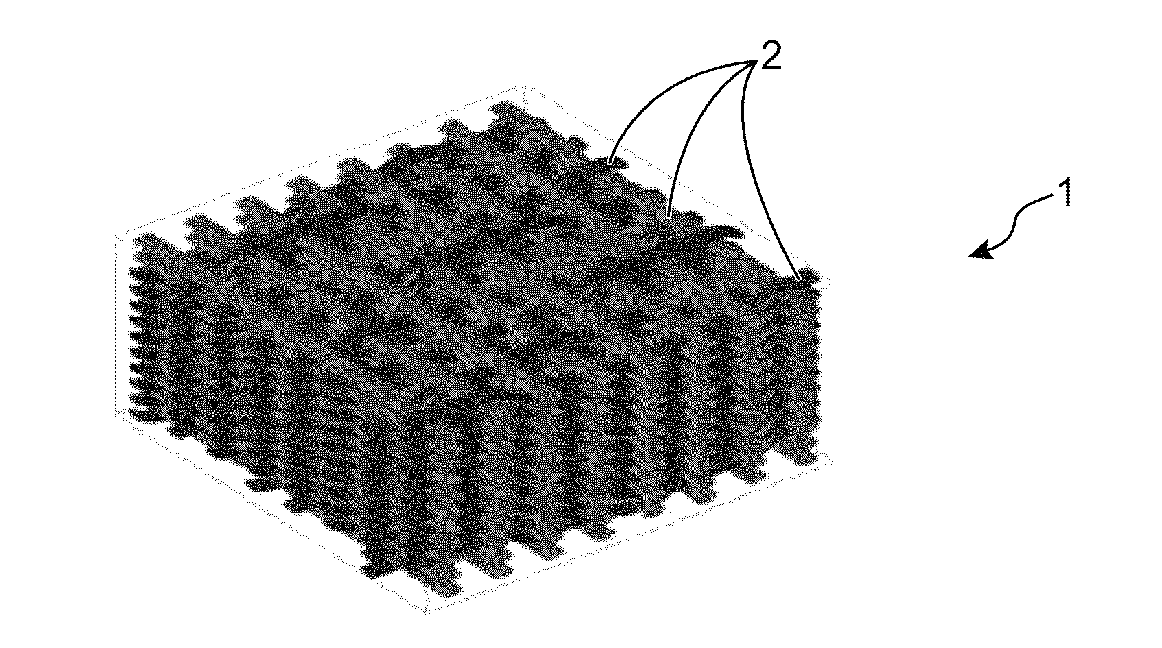
  • Method for producing a composite including a ceramic matrix
  • Method for producing a composite including a ceramic matrix
  • Method for producing a composite including a ceramic matrix

Examples


Embodiment Construction

[0028]This aim is attained thanks to a method for producing a part made of ceramic material matrix and ceramic material fibres composite material, the method comprising the following successive steps:[0029]formation of a fibrous preform by intertwining threads constituted of ceramic material fibres on a contact surface of a support element reproducing the internal and / or external shape of the part to be produced;[0030]partial densification of the fibrous preform at a temperature below the melting temperature of the material of the support element and below the melting temperature of the material of the fibres of the preform, said partial densification resulting in a consolidated fibrous preform comprising a matrix volume fraction above 5% and at the most equal to 40% of the matrix volume of the part to be produced;[0031]removal of the support element from the consolidated fibrous preform by chemical attack of the contact surface of the material of the support element;[0032]densifica...


PUM

PropertyMeasurementUnit
volume fractionaaaaaaaaaa

Abstract

A method for producing a part made of ceramic matrix and ceramic fibers composite material. It comprises: the formation of a fibrous preform by intertwining threads constituted of ceramic material fibers on a contact surface of a support element reproducing the internal and / or external shape of the part to be produced; the partial densification of the fibrous preform at a temperature below the melting temperature of the material of the support element and below the melting temperature of the material of the fibers of the preform, said partial densification resulting in a consolidated fibrous preform comprising a matrix volume fraction above 5% and at the most equal to 40% of the matrix volume of the part to be produced; the removal of the support element from the consolidated fibrous preform by chemical attack of the contact surface of the material of the support element; the densification of the consolidated preform, carried out at a temperature below the melting temperature of the fibers of said preform.

Description

CROSS REFERENCE TO RELATED APPLICATIONS OR PRIORITY CLAIM[0001]This application is a National Phase of PCT / EP2012 / 050979, filed Jan. 23, 2012, entitled, “Method For Producing A Composite Including A Ceramic Matrix”, which claims the benefit of French Patent Application No. 11 51825, filed Mar. 7, 2011, the contents of which are incorporated herein by reference in their entirety.TECHNICAL FIELD[0002]The present invention relates to the manufacture of parts made of reinforced composite materials.[0003]In particular, the invention relates to a method for manufacturing a part made of ceramic matrix composite material.PRIOR ART[0004]Parts made of ceramic matrix composite materials (also known as CMC materials) are characterised by remarkable mechanical properties, particularly in terms of hardness, tenacity, wear resistance and resistance to mechanical and thermal shocks.[0005]Due to these particular properties, parts made of ceramic matrix composite materials are particularly appreciate...

Claims


Application Information

Patent Timeline
Patent Type & Authority Patents(United States)
IPC IPC(8): C04B35/565B28B7/34B28B23/00C04B35/80C04B35/83G21C3/07G21C21/02
CPCC04B35/565B28B7/342B28B23/0006C04B35/806C04B35/83C04B2235/5244C04B2235/5248C04B2235/5252C04B2235/6028C04B2235/614C04B2235/616G21C3/07G21C21/02C04B35/80Y02E30/30C04B35/00C04B35/622G21C21/00
Inventor SAUDER, CEDRICLORRETTE, CHRISTOPHE
Owner COMMISSARIAT A LENERGIE ATOMIQUE ET AUX ENERGIES ALTERNATIVES
Learn More