Methods and device for low contamination energy generation

a low-contamination energy and energy generation technology, applied in the direction of machines/engines, mechanical equipment, separation processes, etc., can solve the problems of high cost of fuel, and high cost of fuel, and achieve the effect of increasing the load of the engin

Inactive Publication Date: 2015-10-13
CLEAN MARINE
View PDF9 Cites 17 Cited by
  • Summary
  • Abstract
  • Description
  • Claims
  • Application Information

AI Technical Summary

Benefits of technology

[0021]whereby said emitted portion has reduced PM, and reduced NOx content when compared with a reference gaseous effluent stream formed by standard burning of the same fuel in an identical engine to which air and fuel are provided in the same given gas to fuel ratio as above. In some embodiments, the method is a method of low-contamination generation of energy from heavy fuel oil (HFO).
[0108]In another embodiment, the engine is operating in an engine room of a ship or a marine oil exploration unit which may contain multiple engines, at least part of which are burning HFO and using for that purpose an identical or a similar gas mixture. In some embodiments, each engine produces flue gases. In one embodiment, the method of the present invention further comprises combining flue gases of multiple engines or all the engines for treatment in a cyclone as herein described [step (d)]. In one embodiment, the cyclone unit [of step (d)] comprises an exhaust collecting hat element, which facilitates combining of the gases, which may be placed, e.g. as shown in FIG. 1. In some embodiments, each engine has an exhaust pipe which extends to the funnel top. In some embodiments, the collecting hat provides a closed compartment at the funnel top in which all flue gas streams may be combined prior to be directed into the cyclone unit, for example by the operation of the fan unit within the cyclone unit. In one embodiment of the invention, the collecting hat element may comprise a hatch which allows for the by-pass of the cyclone unit, if desired.

Problems solved by technology

Such fuels are quite expensive.
Therefore, typically much coarser (lower quality) fuels are utilized.
Operating EGR systems for marine diesel engines presents complications related to the impurities in the flue gas formed when burning marine fuels (ISO 8217 grades).
PM and SOx present a risk for fouling and corrosion of the turbo charger, of the air cooler and of the scavenging systems employed in marine diesel engines.
Thus, the presence of high levels of PM and SOx negatively impact various engine components, for example, in the turbocharger, where high temperature and corrosion might damage the rotor, rotor shaft and housing.
Similarly, the air cooler is negatively impacted by the presence of high levels of PM and SOx resulting in corrosion.
Reduction of PM and SOx content in the exhaust gas to be recycled is therefore essential and its accomplishment at an acceptable cost presents a major challenge.
In addition, while methods for reduction of PM and SOx content are known, they typically fail to totally eliminate those components.
PM remaining in the treated gas recycled to EGR systems may be more problematic for the EGR system than the PM removed by existing methods and the same situation may arise with regards to the various types of SOx in the gas.
Therefore the prior art does not provide a teaching as to the effect of removal of PM by the prior art methods on the ability of the remaining gas to be used for recycling.

Method used


Image

  • Methods and device for low contamination energy generation
  • Methods and device for low contamination energy generation
  • Methods and device for low contamination energy generation

Examples


examples

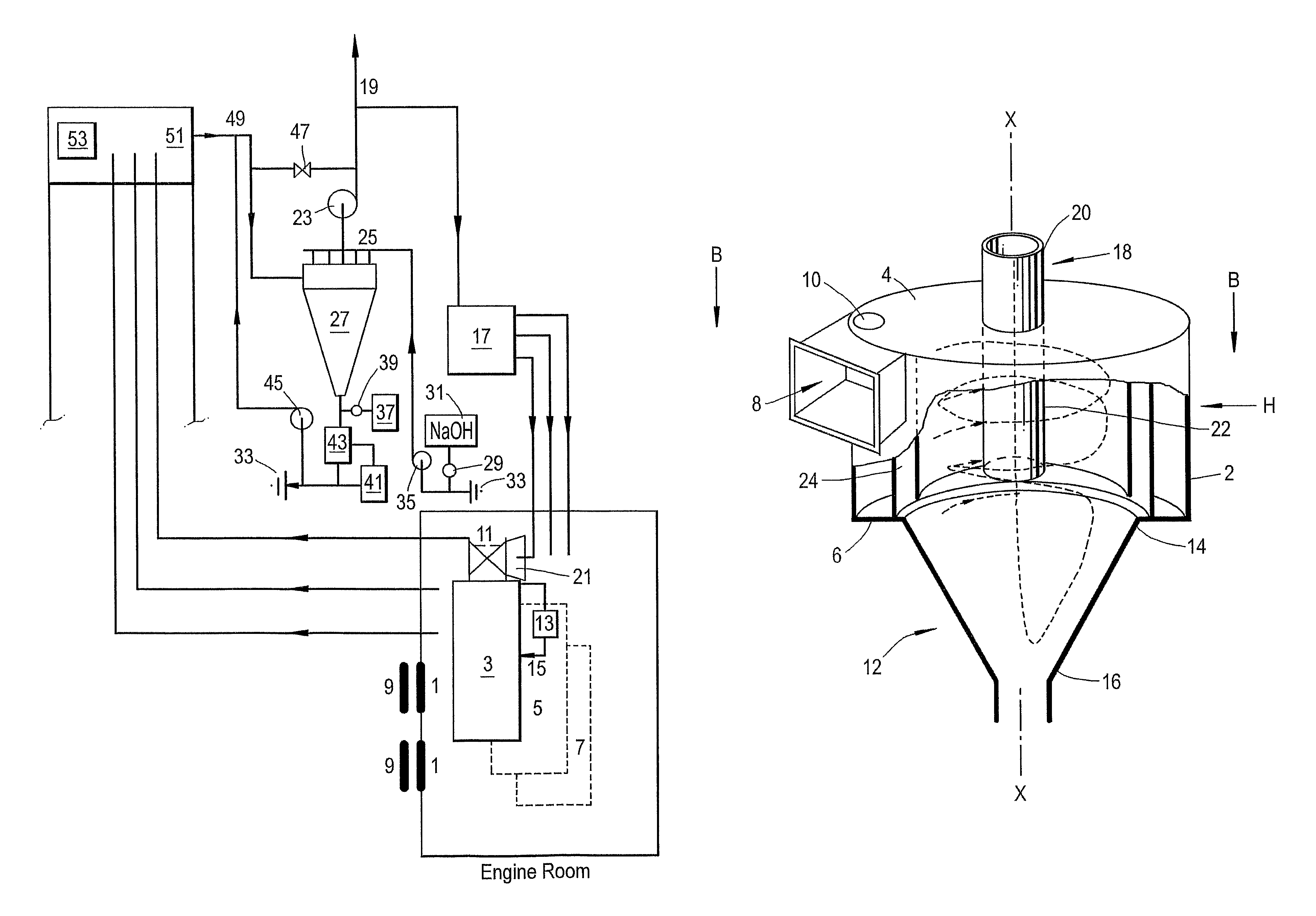
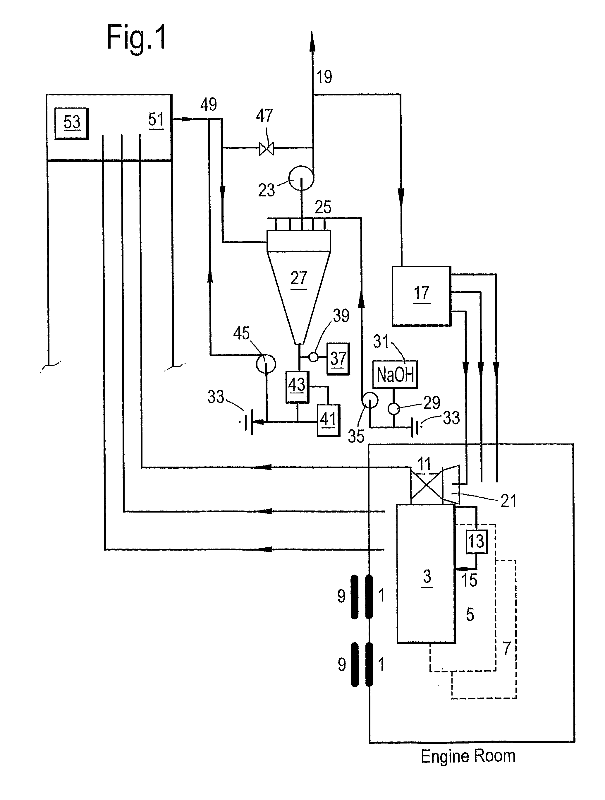
[0152]Referring to FIG. 1, an engine room onboard a ship or oil exploration unit, is fed air through one or more fans (1) to meet the scavenging air requirements for the diesel engines (3) (5) (7) and boilers (not shown) on board such vessels. One or more fans (1) may be turned off during a period of time when the engines are not in use. Filters (9) may or may not be attached to the fan.

[0153]Air in the engine room is drawn in through coarse filter pads (9) into the turbocharger (11) where it is compressed for up to about 1-3 bars (pending engine loads). The heated compressed air is cooled by the air cooler (13) down to about 40-45° C. before accessing the cylinders of diesel engines (3) (5) and (7). The air cooler (13) relies on application of water for cooling, with the amount of water applied being sufficient to keep the scavenging air constant while ambient temperature changes. Conditions will be adjusted to accommodate engine use in different climactic conditions, for example, ...


PUM

PropertyMeasurementUnit
velocityaaaaaaaaaa
v/vaaaaaaaaaa
pressureaaaaaaaaaa

Abstract

A method for low-contamination generation of energy comprising: (a) forming a gas mixture by mixing a treated gaseous effluent stream and air; (b) introducing the gas mixture and fuel at a given gas to fuel ratio into at least one diesel engine (3); (c) burning the fuel in the diesel engine to generate energy and a flue gas stream comprising particulate matter (PM), and nitrogen oxides (NOx); (d) treating at least a portion of the flue gas stream with an aqueous stream in a cyclone unit (27) comprising a housing defined by a cylindrical peripheral wall (2) and provided with at least one inlet opening (10) for receiving flue gas and at least one inlet opening for receiving fluids thereinto and with at least one swirling means, whereby a treated gaseous effluent stream and an aqueous effluent stream are formed; (e) emitting a portion of the treated gaseous effluent stream to form an emitted portion; (f) using a portion of the treated gaseous effluent stream to form the gas mixture, and (g) repeating steps (a) through (f) multiple times.

Description

[0001]This application is the National Stage of International Application No. PCT / IL2009 / 001100 filed on Nov. 23, 2009, which claims the benefit of Israeli Patent Application No. 196,231, filed on Dec. 28, 2008, both of which are incorporated herein by reference in their entirety.FIELD OF THE INVENTION[0002]This invention relates, inter alia, to low-contamination energy generation methods and devices for effecting the same. The methods and devices are useful for removal and / or destruction of diesel engine exhaust pollutants such as particulate matter, nitrogen oxides and sulfur oxides.BACKGROUND OF THE INVENTION[0003]Diesel engines emit flue gas, which is released to the atmosphere. The flue gas contains pollutants, which include particulate matter (PM) comprising, among others, soot, ash, organic compounds and in many cases sulphur compounds. Sulphur compounds concentration in the flue gas is correlated with the concentration of sulphur compounds in the fuel, typically measured as ...

Claims


Application Information

Patent Timeline
Patent Type & Authority Patents(United States)
IPC IPC(8): F01N3/00B01D45/12B01D47/06B01D50/00F01N13/00F01N3/037F02M25/07F01N3/04F02B29/04
CPCF01N13/004B01D45/12B01D47/06B01D50/004F01N3/037F02B29/0437F02M25/074F02M25/0743F01N3/04Y02T10/20Y02T10/121Y02T10/146F02M26/35F02M26/37Y02T10/12B01D50/40
Inventor HOY-PETERSEN, NILS CHRISTIANEYAL, AHARON M.CANARI, RIKI
Owner CLEAN MARINE
Why Eureka
Try Eureka