Liquid crystal display device, method for driving thereof and electronic apparatus

a display device and liquid crystal technology, applied in the field of display, can solve the problems of reducing image quality under indoor fluorescent light, fundamental solution not achieved, and deteriorating visibility, and achieve excellent visibility and secure visibility

Inactive Publication Date: 2015-10-13
SEMICON ENERGY LAB CO LTD
View PDF114 Cites 7 Cited by
  • Summary
  • Abstract
  • Description
  • Claims
  • Application Information

AI Technical Summary

Benefits of technology

[0007]Thus, an object of the invention is to provide a display device in which display can be recognized even when it is set under from a dark place to strong external light.
[0011]The structure of a transistor is not specifically limited and various modes may be adopted. For example, it is possible to adopt a multi-gate structure having two or more gates. When using the multi-gate structure, an off-current can be reduced, the withstand voltage of a transistor can be increased to improve reliability, and variations in characteristics can be suppressed when the transistor operates in the saturation region since a drain-source current does not change much even when a drain-source voltage changes. Further, gate electrodes may be provided on and under a channel. The structure where gate electrodes are provided on and under a channel allows a channel region to be increased; therefore, a current value can be increased and a depletion layer is easily formed to increase the S value. Further, a gate electrode may be provided on a channel or a under a channel. A staggered structure or a reversed staggered structure may be adopted. A channel region may be divided into a plurality of regions, and these regions may be connected in parallel or in series. A source electrode or a drain electrode may overlap a channel (or a part of it). The structure where a source electrode or a drain electrode overlaps a channel (or a part of it) prevents charges from being accumulated in a part of the channel, which may cause unstable operation. In addition, an LDD region may be provided. When providing the LDD region, an off-current can be reduced, the withstand voltage of a transistor can be increased to improve reliability, and variations in characteristics can be suppressed when the transistor operates in the saturation region, since a drain-source current does not change much even when a drain-source voltage changes.
[0027]According to the invention, a display device whose visibility is excellent can be provided by controlling the number of gray scales of a display image depending on external light intensity. That is, a display device which secures visibility can be obtained in a wide range from under fluorescent light in a dark place or indoor to under outdoor sunlight.

Problems solved by technology

A liquid crystal panel has good visibility in an indoor environment of from 300 to 700 lux, but the visibility deteriorates significantly in an outdoor environment of 1,000 lux or more, which has been a problem.
Although there is a reflective liquid crystal panel having a structure in which the pixel electrode reflects external light, the image quality is lowered under an indoor fluorescent light, and a fundamental solution has not been achieved.
That is, ensuring of visibility in a wide range from a dark place or under an indoor fluorescent light to under outdoor sunlight has not been achieved yet.

Method used


Image

  • Liquid crystal display device, method for driving thereof and electronic apparatus
  • Liquid crystal display device, method for driving thereof and electronic apparatus
  • Liquid crystal display device, method for driving thereof and electronic apparatus

Examples


embodiment modes

[0064]Hereinafter, the embodiment modes of the present invention will be described with reference to the accompanying drawings. However, it is to be understood that various changes and modifications will be apparent to those skilled in the art. Therefore, unless such changes and modifications depart from the scope of the invention, they should be construed as being included therein.

embodiment mode 1

(Embodiment Mode 1)

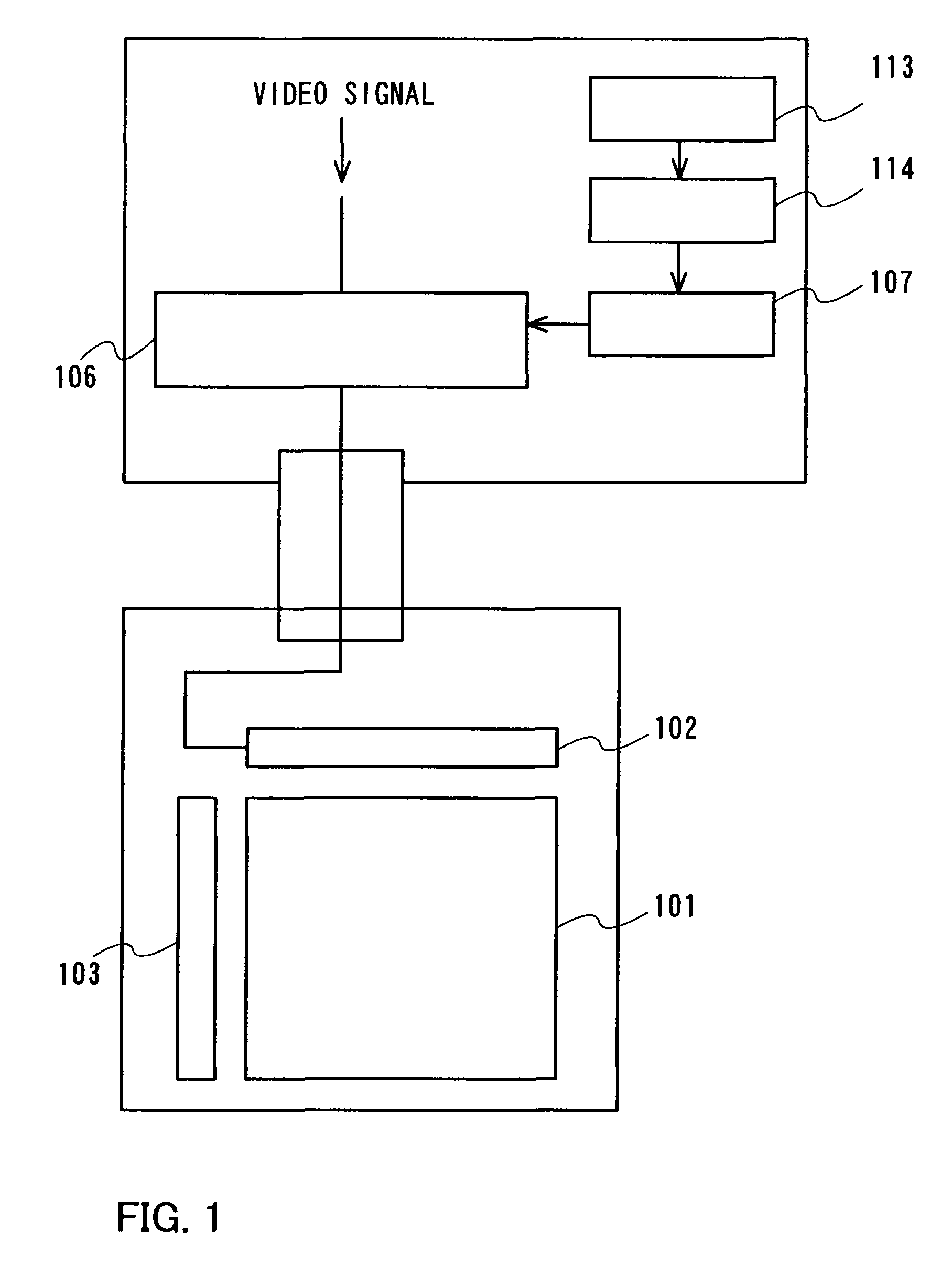
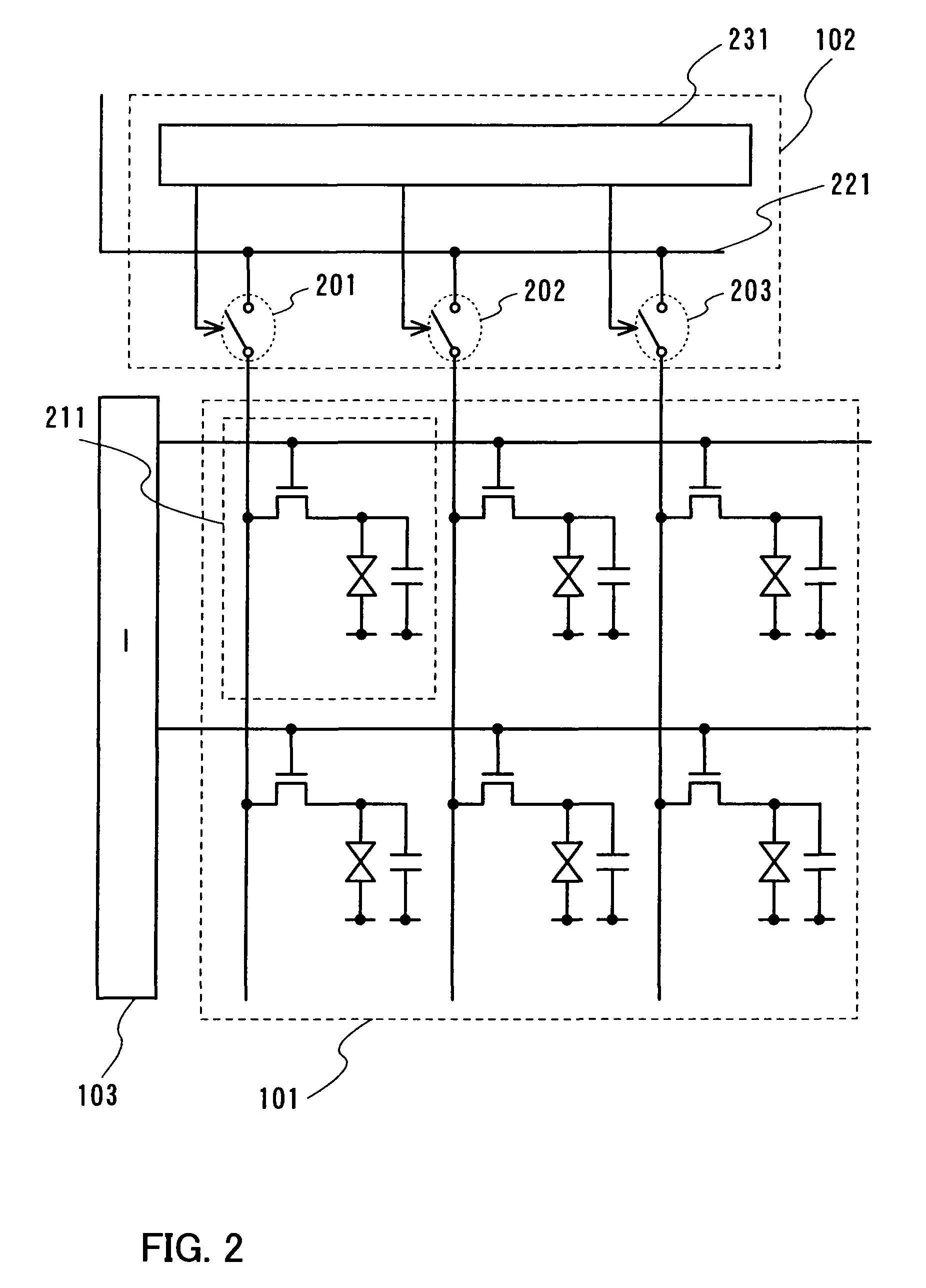
[0065]FIG. 1 is an entire block diagram. A source driver 102 and a gate driver 103 are provided for driving a pixel array 101. A video signal is inputted to the source driver 102. Note that a plurality of source drivers 102 and a plurality of gate drivers 103 may be provided.

[0066]An optical sensor 113 detects external light (external light which a display device receives). The output is supplied to an amplifier 114. The amplifier 114 amplifies an electrical signal that the optical sensor 113 outputs and the amplified electrical signal is supplied to a controller 107. When an electrical signal outputted by the optical sensor 113 outputs is large enough, the amplifier 114 is not required to be provided.

[0067]Note that a source driver or one portion thereof are not on the same substrate as the pixel array 101, and for example, using an external IC chip, and the source driver or one portion thereof can be composed.

[0068]Note that the amplifier 114 or the optical sens...

embodiment mode 2

(Embodiment Mode 2)

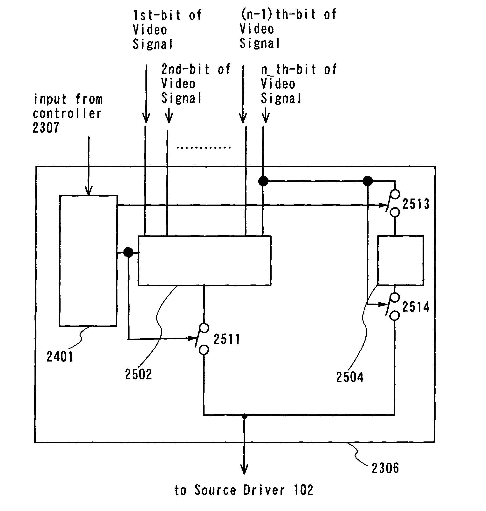
[0118]Embodiment Mode 1 describes the case where a video signal to be inputted to the display mode-specific video signal generation circuit 106 is an analog value. Next, described is a case where a digital value is inputted.

[0119]FIG. 24 is an entire block diagram. A video signal to be inputted to the source driver 102 is generated in accordance with each display mode in a display mode-specific video signal generation circuit 2306. The display mode-specific video signal generation circuit 2306 is controlled using a controller 2307. Moreover, an original digital video signal is inputted to the display mode-specific video signal generation circuit 2306. Then, by using an original video signal, a video signal in accordance with each display mode is generated and outputted to the source driver 102 in the display mode-specific video signal generation circuit 2306.

[0120]An optical sensor 2313 detects external light (external light which a display device receives). The o...


PUM


Abstract

The liquid crystal display device performs display by changing the number of gray scales depending on external light intensity, and switches the display mode in accordance with a content to be displayed on a display. By controlling a display mode-specific video signal generation circuit depending on external light intensity, an inputted video signal is outputted as an analog value, is outputted with a digital value of a binary, or is outputted with a multiple digital value. As a result, display gradation of a pixel changes timely. Accordingly, a clear image can be displayed. For example, a display device which secures visibility can be obtained in a wide range from under fluorescent light in a dark place or indoor to under outdoor sunlight.

Description

BACKGROUND OF THE INVENTION[0001]1. Field of the Invention[0002]The invention relates to a display device provided with a display screen which can display a character, a still image, a moving image, or the like, and relates to a technique for improving visibility of a display screen in various operating environments.[0003]2. Description of the Related Art[0004]A variety of electric appliances with a display screen structured by a liquid crystal panel, including a cell-phone, are prevalent. A liquid crystal panel has characteristics of being thin and light, and mobile laptop personal computers provided with a liquid crystal panel are produced. Furthermore, terminal devices called PDA (Personal Digital Assistant) are produced in large numbers, and becoming common.[0005]As for display panels used in this way, not limited to a liquid crystal panel, the visual image quality is regarded as important, and panels provided with a function of adjusting the brightness and contrast automaticall...

Claims


Application Information

Patent Timeline
Patent Type & Authority Patents(United States)
IPC IPC(8): G09G3/36G09G3/20
CPCG09G3/3688G09G3/20G09G2310/0294G09G2340/0428G09G2370/08G09G2320/0271G09G2360/144G02F1/133
Inventor YAMAZAKI, SHUNPEIKOYAMA, JUNTANADA, YOSHIFUMIOSAME, MITSUAKIKIMURA, HAJIMEFUKUMOTO, RYOTAYANAI, HIROMI
Owner SEMICON ENERGY LAB CO LTD
Why Eureka
Try Eureka