Power conversion device

a power conversion device and power technology, applied in the direction of dynamo-electric converter control, program control, instruments, etc., can solve the problem of larger device size, and achieve the effect of improving performan

Active Publication Date: 2015-10-13
MITSUBISHI ELECTRIC CORP
View PDF21 Cites 4 Cited by
  • Summary
  • Abstract
  • Description
  • Claims
  • Application Information

AI Technical Summary

Benefits of technology

[0016]In order to suppress a beat in an inverter output current resulting from a pulsation of a frequency component twice the frequency of a single-phase AC voltage superimposed on a DC voltage, second compensation means taking responsiveness of a motor into consideration is provided in addition to a function of first compensation means for extracting and then suppressing the frequency component twice the frequency of the single-phase AC voltage. Owing to this configuration, it becomes possible to enhance performance to suppress a beat in an inverter output current without depending on a capacity of a capacitor provided to converter means and response characteristics of the motor.

Problems solved by technology

Also, such an increase of the capacity raises a problem that a size of the device becomes larger.

Method used


Image

  • Power conversion device
  • Power conversion device
  • Power conversion device

Examples


first embodiment

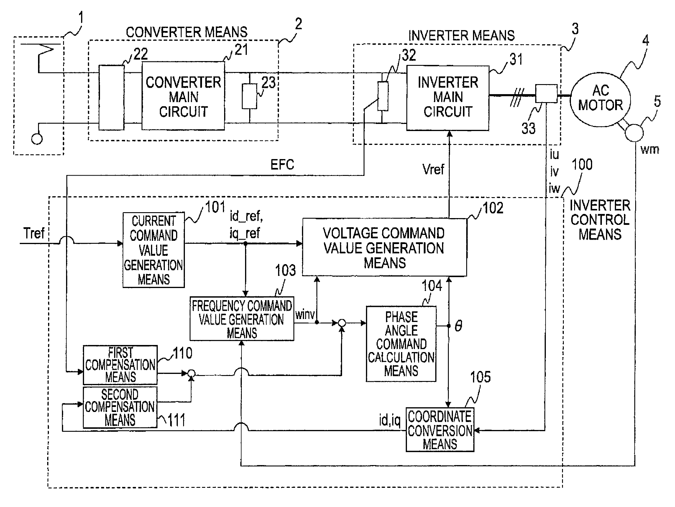
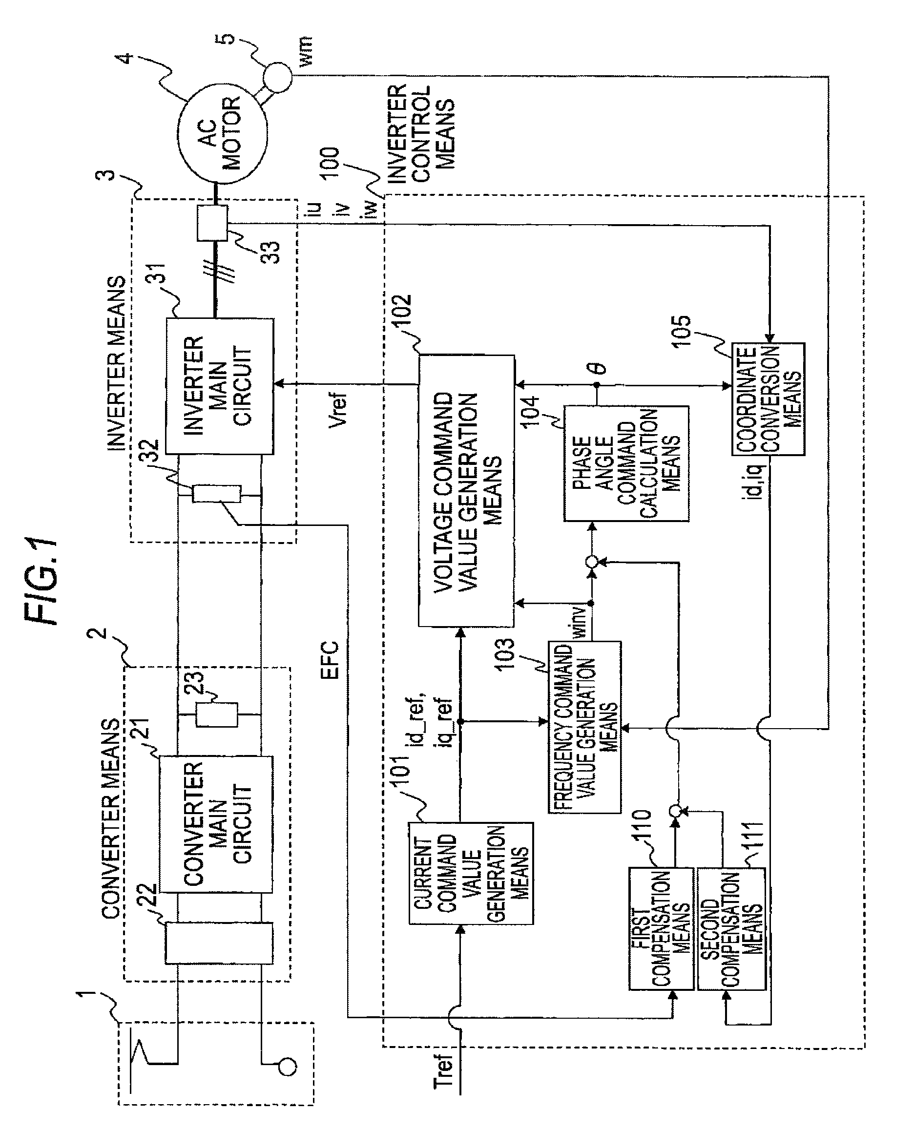
[0041]FIG. 1 shows an overall configuration of a power conversion device of a first embodiment. Referring to the drawing, a single-phase AC power supply 1 is formed of wiring or a pantograph in the case of an electric rail vehicle using AC wiring and supplies converter means 2 with a single-phase AC voltage from a transformer station.

[0042]The converter means 2 is formed of a converter main circuit 21 made up of semiconductor switching elements, an input transformer 22 that steps down a voltage of the single-phase AC power supply 1, a smoothing capacitor 23, and so on, and is furnished with a function of outputting a DC voltage by rectifying a single-phase AC voltage. Because the principle of its operation is known and not directly relevant the content of this application, a description is omitted herein.

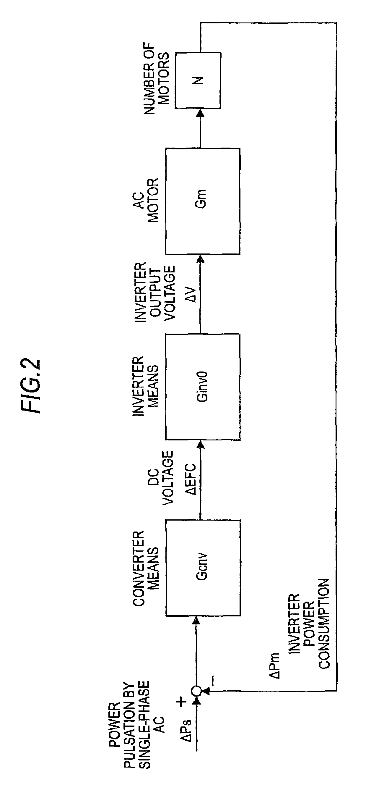
[0043]In a case where single-phase AC is rectified, a DC voltage as an output is superimposed with a pulsation having a frequency component twice the frequency of a single-phase AC ...

second embodiment

[0123]FIG. 17 shows a power conversion device of a second embodiment. The single-phase AC power supply 1, the converter means 2, the inverter means 3, the AC motor 4, and the speed detection means 5 are the same as the respective counterparts in the first embodiment above, and a description is omitted herein.

[0124]A difference from the inverter control means 100 of the first embodiment above and the second compensation means 111 of the first embodiment above are that alpha-numeral 100b denotes inverter control means and an input to second compensation means 111b is the DC voltage EFC instead of the q-axis current. Even when configured in this manner, it becomes possible to obtain the effects same as those of the first embodiment above.

[0125]FIG. 18 shows a block diagram of the transmission characteristics of FIG. 17. Herein, the second compensation means 111b has transmission characteristics Gcp_2 made up of high-pass processing and gain processing and set as in Equation (17) below ...

third embodiment

[0145]FIG. 24 shows a configuration of a third embodiment. The single-phase AC power supply 1, the converter means 2, and the inverter means 3 are the same as the respective counterparts of the first and second embodiments above. On the other hand, a difference from the first and second embodiments above is that an AC motor 4c is a synchronous motor and alpha-numeral 5c denotes position detection means for detecting a magnetic pole position. In addition, inverter control means 100c is means corresponding to a synchronous motor.

[0146]In a case where the AC motor 4c is a synchronous motor, vector control is performed using a rotor magnetic pole position in the synchronous motor as a reference axis. In other words, a magnetic pole position is detected by the phase detection means 5c and an output current of the inverter means is converted by coordinate conversion on dq axes by the coordinate conversion means 105c according to the detected magnetic pole position. Also, current command v...


PUM


Abstract

A power conversion device formed of a converter for rectifying a single-phase AC voltage to a DC voltage and an inverter for driving an AC motor by converting the DC voltage to an AC voltage includes: a first compensation unit that uses a frequency component twice the frequency of the single-phase AC voltage with respect to the DC voltage outputted from the converter or a current outputted from the inverter as a compensation value for at least one of a torque command value, a current command value, a voltage command value, a frequency command value, and a phase angle command value; and a second compensation unit that uses the DC voltage outputted from the converter or a current outputted from the inverter after being subjected to low frequency cut-off processing and gain processing.

Description

TECHNICAL FIELD[0001]The present invention relates to a power conversion device formed of a converter that converts AC to DC and an inverter that converts a DC output of the converter to AC, and more particularly, to a power conversion device suppressing a beat phenomenon accompanying a rectification pulsation resulting from rectification by the converter when an AC motor is driven at a variable speed by the inverter.BACKGROUND ART[0002]For example, a drive device of an electric car adopts a configuration in which AC from a power collector, such as a pantograph sliding on wiring connected to an AC power supply, is converted to DC by a converter via a transformer, and DC is further converted to three-phase AC power via an inverter so as to drive a three-phase induction motor.[0003]In the power conversion device in the related art of this type, a DC voltage at an output end of the converter is superimposed with a component that pulsates at twice the frequency of an AC power-supply vol...

Claims


Application Information

Patent Timeline
Patent Type & Authority Patents(United States)
IPC IPC(8): H02P27/04H02P27/06G05B19/00B60L15/02H02P29/00H02P21/05B60L9/00H02M1/15H02M5/458H02P21/00H02P21/22H02P23/04H02P23/07H02P23/12
CPCH02P27/06B60L9/005B60L15/025G05B19/00H02P29/0038H02P21/05H02P2207/01H02M1/15H02M5/4585H02P29/50Y02T10/64
Inventor YAMASAKI, HISANORIHATANAKA, KEITAKITANAKA, HIDETOSHI
Owner MITSUBISHI ELECTRIC CORP
Why Eureka
Try Eureka