
Solid state catholytes and electrolytes for energy storage devices

a technology of solid state catholytes and electrolyte materials, which is applied in the direction of sustainable manufacturing/processing, cell components, batteries, etc., can solve the problems of liquid electrolyte outgassing at high voltage, threat of thermal runaway, and limited storage capacity of popular apparatus, so as to improve the total ionic conductivity, improve the effect of ionic conductivity and increase the mass loading of active materials

Active Publication Date: 2015-10-27
QUANTUMSCAPE CORP
View PDF13 Cites 37 Cited by
  • Summary
  • Abstract
  • Description
  • Claims
  • Application Information

AI Technical Summary

Benefits of technology

The present invention relates to solid state battery cells and techniques to improve their performance. Specifically, the invention provides a method and structure for a catholyte material that increases total ionic conductivity for the cathode, allowing for higher mass loading of active material, faster charge / discharge, and a wider range of operating temperature. This results in a fully solid state battery with improved energy density and safer operation. The invention involves a novel dopant configuration of the LiaMPbSc material, which can be applied to solid state battery cells. Overall, the invention offers a more efficient and reliable solution for solid state battery development.

Problems solved by technology

Although highly successful, these popular apparatus are limited by storage capacity and in particular battery capacity.
Liquid electrolytes suffer from outgassing at high voltage and pose a threat of thermal runaway due to the enthalpy of combustion of the solvents.
State of the art solid state batteries are not ready for mass market adoption due to limited power density, mass loading, and manufacturability.

Method used


Image

  • Solid state catholytes and electrolytes for energy storage devices
  • Solid state catholytes and electrolytes for energy storage devices
  • Solid state catholytes and electrolytes for energy storage devices

Examples


Embodiment Construction

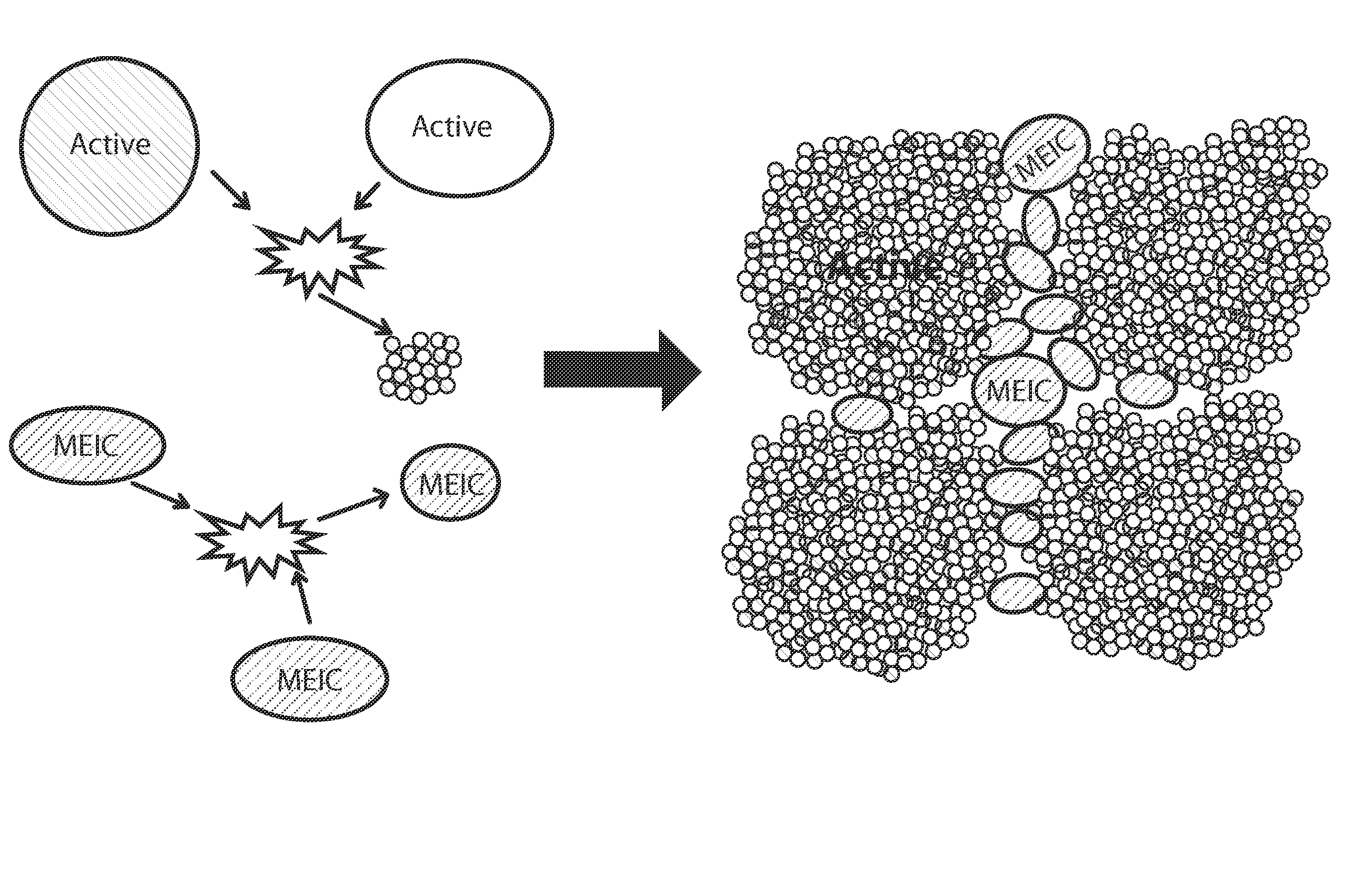
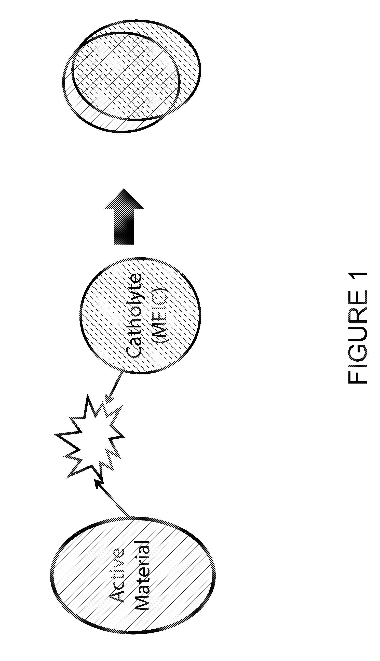
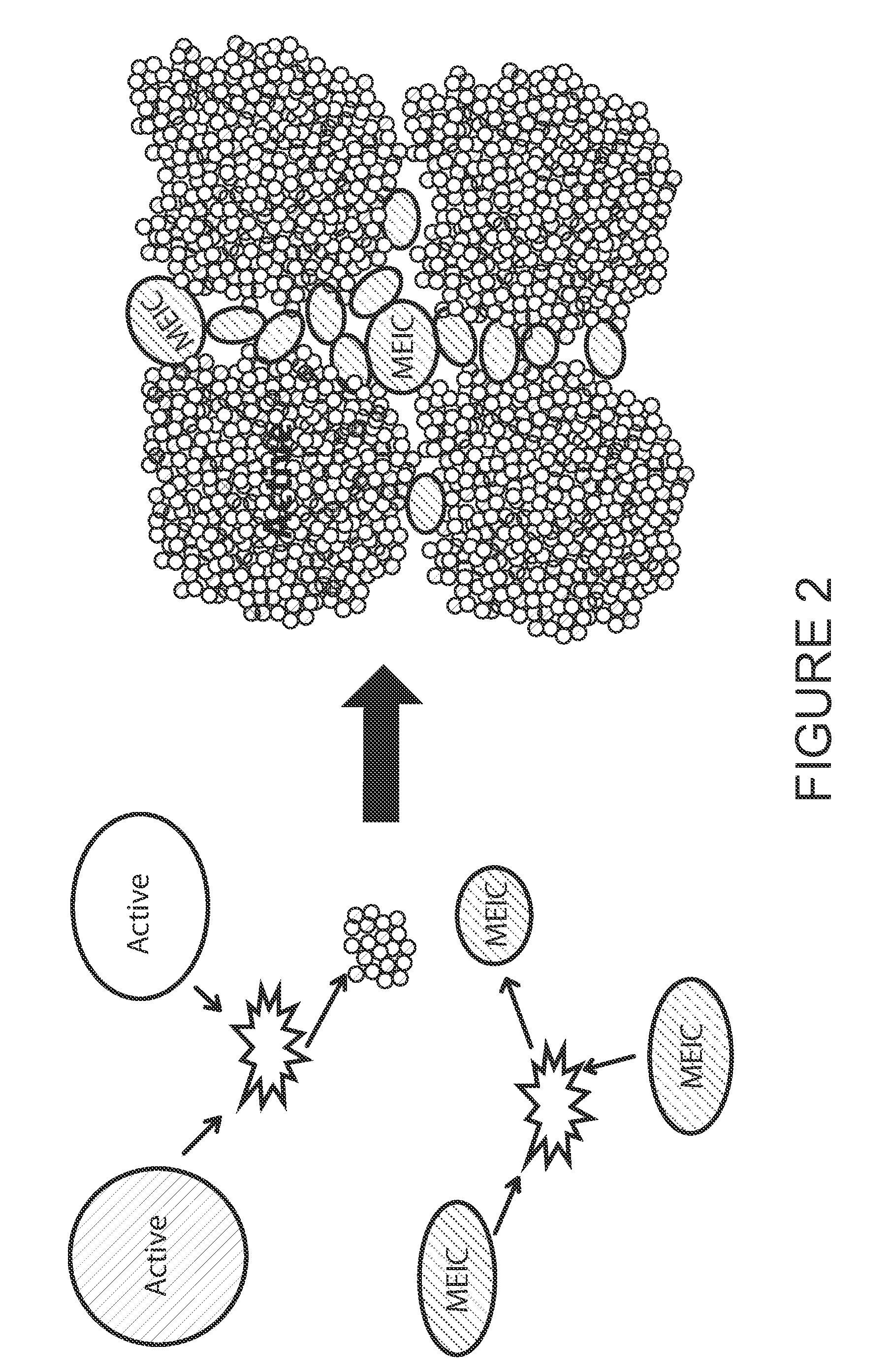
[0057]According to an embodiment of the present invention, techniques related to a solid catholyte or electrolyte material having desired ion conductivity are provided. More particularly, an embodiment of the present invention provides a method and structure for a catholyte material to improve a total ionic conductivity for a cathode to allow for higher mass loading of an active material, faster charge / discharge, and a wider range of operating temperature. Merely by way of example, the invention has been applied to solid state battery cells, although there can be other applications.

[0058]As background, poor ionic conductivity of the cathode in a battery imposes strong limitations to overall performance. By mixing the low ionic conductivity cathode active material with a high ionic conductivity ceramic catholyte, it is possible to improve the overall cathode conductivity. In this description, the ceramic catholyte is either LGPS or LSPS, which possesses Li ion conductivity greater th...


PUM

PropertyMeasurementUnit
median diameteraaaaaaaaaa
porosityaaaaaaaaaa
porosityaaaaaaaaaa

Abstract

The present invention provides an energy storage device comprising a cathode region or other element. The device has a major active region comprising a plurality of first active regions spatially disposed within the cathode region. The major active region expands or contracts from a first volume to a second volume during a period of a charge and discharge. The device has a catholyte material spatially confined within a spatial region of the cathode region and spatially disposed within spatial regions not occupied by the first active regions. The device has a protective material formed overlying exposed regions of the cathode material to substantially maintain the sulfur species within the catholyte material. Also included is a novel dopant configuration of the LiaMPbSc (LMPS) [M=Si, Ge, and / or Sn] containing material.

Description

CROSS-REFERENCE TO RELATED APPLICATIONS[0001]This application is a continuation of PCT Application No. PCT / US2014 / 038238, filed May 15, 2014, entitled SOLID STATE CATHOLYTE OR ELECTROLYTE FOR BATTERY USING LiaMPbSc (M=Si, Ge, and / or Sn), which claims priority to U.S. Provisional Patent Application No. 61 / 823,407, filed May 13, 2013, and U.S. Provisional Patent Application No. 61 / 935,956, filed Feb. 5, 2014, the disclosures of which are incorporated herein by reference in their entirety.BACKGROUND[0002]In some examples, an embodiment of the present invention relates generally to a solid catholyte or electrolyte material having desired ion conductivity. More particularly, an embodiment of the present invention provides a method and structure for a catholyte material to improve a total ionic conductivity for a cathode to allow for higher mass loading of an active material, faster charge / discharge, and a wider range of operating temperature. Merely by way of example, the invention has b...

Claims


Application Information

Patent Timeline
Patent Type & Authority Patents(United States)
IPC IPC(8): H01M4/62H01M10/0562H01M4/131H01M10/0525
CPCH01M10/0562H01M4/131H01M4/62H01M10/0525H01M2220/20H01M2220/30H01M2300/0068H01M2300/0071H01M2300/0074H01M4/366H01M10/056H01M4/136H01M4/582C01B33/00C04B35/547C04B35/6261C04B35/6262C04B35/62645C04B2235/3203C04B2235/446C04B2235/447C04B2235/428Y02E60/10H01M4/505H01M4/525Y02P70/50Y02T10/70H01M50/46C01P2006/40H01M4/5825H01M4/624
Inventor CHAO, CHENG CHIEHCHEN, ZHEBOHOLME, TIMMAYER, MARIE A.RILEY, JR., GILBERT N.
Owner QUANTUMSCAPE CORP
Learn More