High efficiency mono-order concave diffraction grating

a diffraction grating, high efficiency technology, applied in the field of diffraction gratings, can solve the problems of large footprint of cascaded mach-zehnder filters compared to arrayed waveguide gratings, large footprint of each new technique, and inability to meet the requirements of light efficiency coupling, etc., to achieve the effect of maximizing light efficiency coupling

Active Publication Date: 2015-11-03
VALORBEC S E C
View PDF29 Cites 28 Cited by
  • Summary
  • Abstract
  • Description
  • Claims
  • Application Information

AI Technical Summary

Benefits of technology

[0019]In some embodiments the elements providing the reflection each have a substantially elliptical shape to provide output efficiency and aberration-free focusing with foci located at a device input and a device output.
[0040]In some embodiments the refractive index difference between the elements providing the reflection is moderate (e.g. 1.5 / 1) and consequently the number of required elements is moderate.
[0068]In some embodiments the channel waveguides have a free orientation, in particular the one to maximize the light efficiency coupling into them.

Problems solved by technology

These early implementations are bulky and suffer from problems relating to size, alignment, packaging, and instability over time.
Such implementations have lead to substantial improvements compared to the earlier technologies, but each of these new techniques still has some limitations.
Cascaded Mach-Zehnder filters have a large footprint compared to arrayed waveguide gratings and concave diffraction gratings, especially for large numbers of channels.
The metallization of the grating is delicate in the fabrication process, as it requires an angled deposition.
Although metalized, the grating configuration has losses, and the efficiency is limited.
These alternatives have their own theoretical sources of loss as well as losses due to fabrication, such as rounding of corners at the facets of the grating.
Also, as the number of channels increases, limitations such as phase errors, and crosstalk occur, which restrict performance.
In addition, the physical size of the device increases with the number of channels, making the device larger than desirable for some uses.
The efficiency of AWGs has a further limitation, namely due to the fact that there is a field distribution mismatch at a connection between the first slab free space region 120 and the array of waveguides 130, a part of the transmitted light is lost and may propagate as stray light causing deteriorating crosstalk with other channels.
Overall size of devices is also a major issue driving improvements in this field.

Method used


Image

  • High efficiency mono-order concave diffraction grating
  • High efficiency mono-order concave diffraction grating
  • High efficiency mono-order concave diffraction grating

Examples


Embodiment Construction

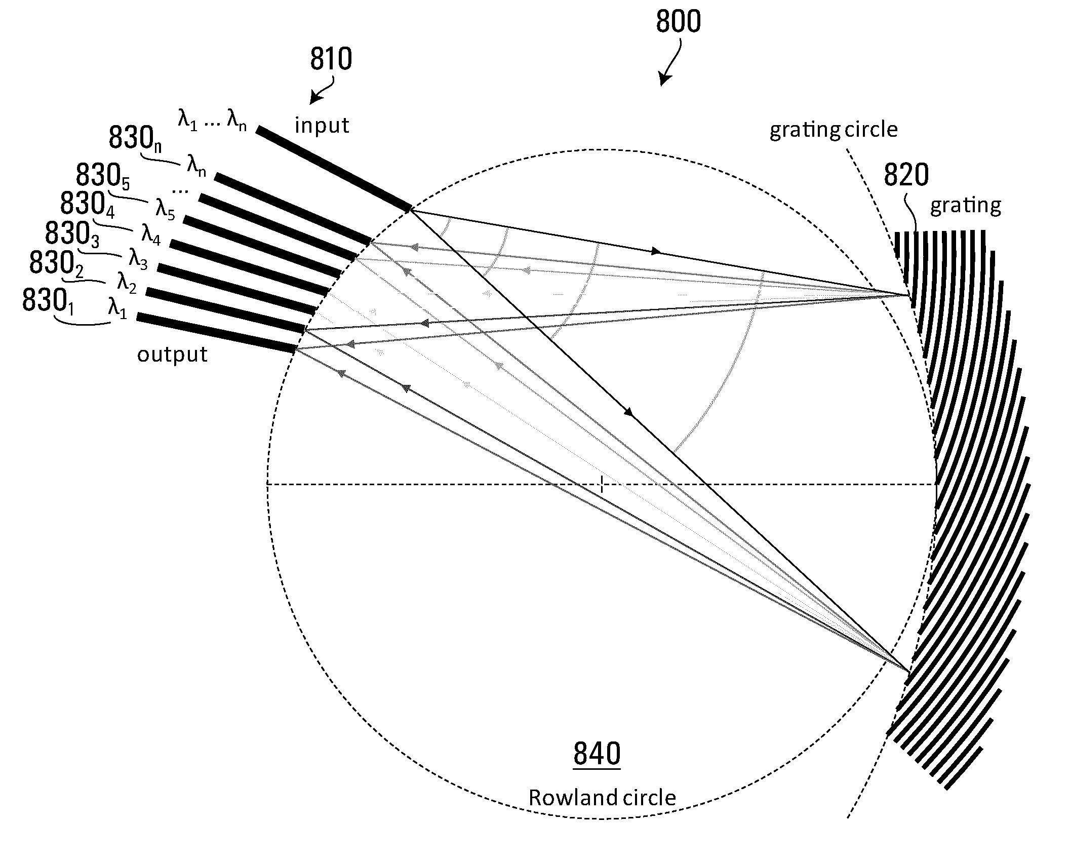
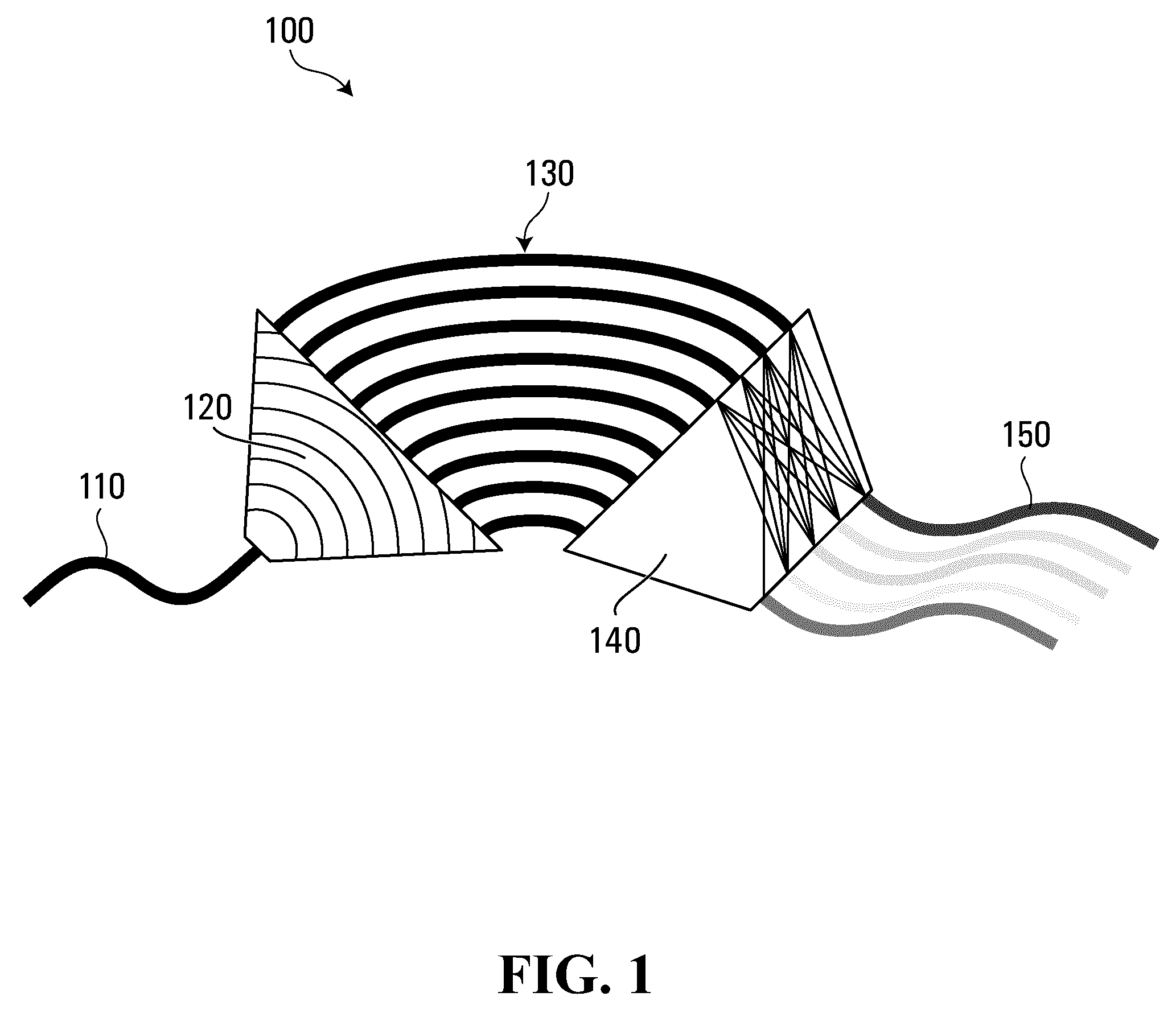
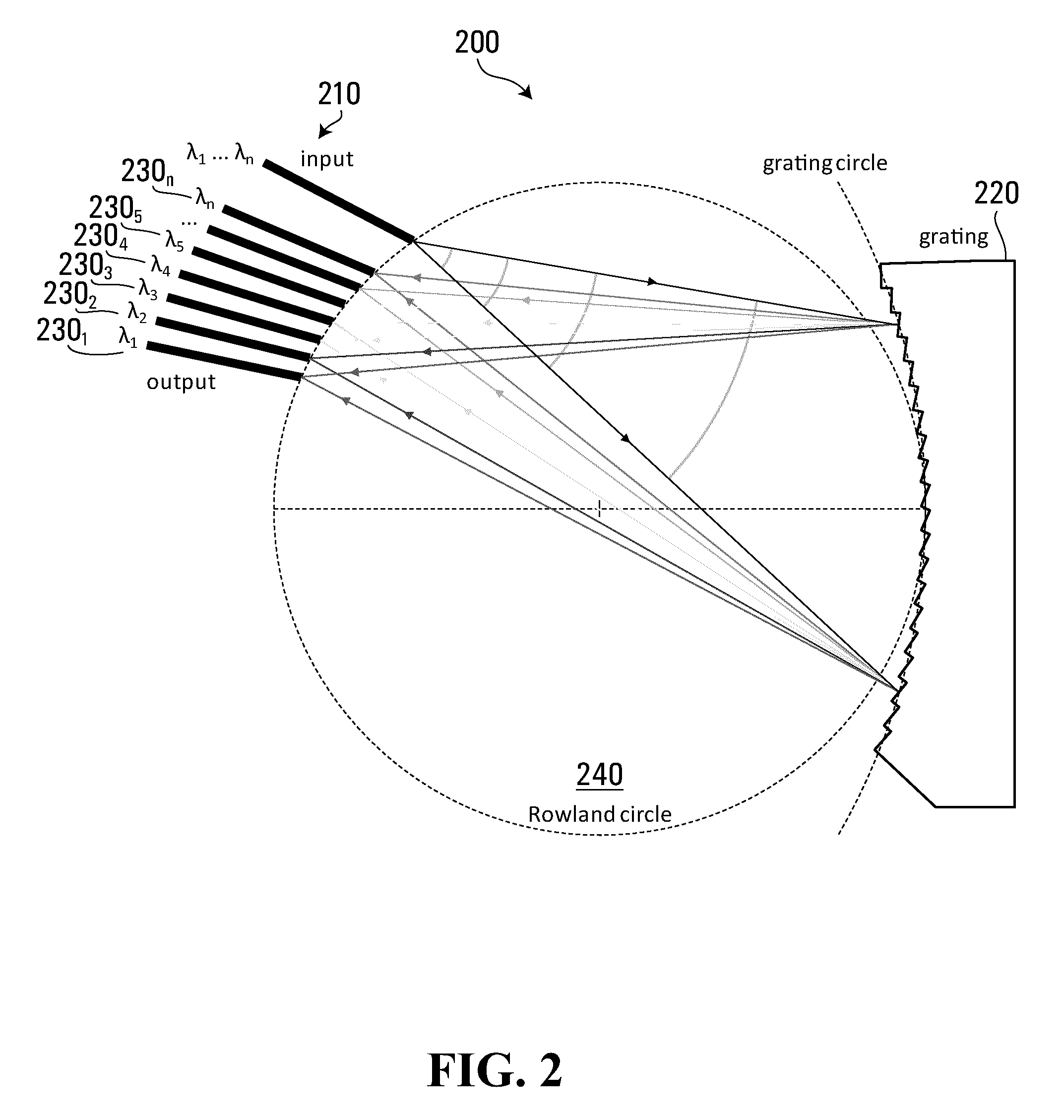
[0120]Some aspects of the invention deal with using a concave diffraction grating, in which the classical grating is being replaced by a new configuration. In some embodiments, metallization is avoided by replacing the metalized grating by a curved dielectric mirror. This eliminates the difficulty of deposition and enables a grating approaching 100% efficiency. It also reduces sensitivity to polarization. In other embodiments, deep etching is replaced by a shallow etching or other techniques that modify the index of refraction (doping, etc), possibly making it even easier to fabricate. In a further embodiment, metal is used in thin lines, not in a single piece, and has less polarization sensitivity than a single piece metal grating because there are substantially no facet edges. Consequently, present limitations of concave diffraction gratings can be substantially alleviated, resulting in a high-quality device for WDM devices and micro-spectrometer.

[0121]Some embodiments of the inve...


PUM


Abstract

A concave diffraction grating for integrated optics is constructed by replacing the reflective metallic part by either multiple thin elements of metal or multiple elements of dielectric material, each partially reflecting the light, and arranged on elliptical fashion in order to distribute the diffraction / reflection of light and provide aberration-free focusing, by combining diffraction condition and Bragg condition of these curved reflectors.

Description

RELATED APPLICATION[0001]This application claims the benefit of and is a National Phase Entry of International Application Number PCT / CA2012 / 050706 filed Oct. 5, 2012, and claims the benefit of U.S. Provisional Patent Application No. 61 / 544,093 filed on Oct. 6, 2011, both of which are incorporated herein by reference in their entirety.TECHNICAL FIELD[0002]The application relates to diffraction gratings for planar optics.BACKGROUND[0003]Multiplexing and demultiplexing in optical communication systems are implemented in multiple different forms. Early implementations included using: 1) bulk optics with a diffraction grating and lens to spread wavelengths angularly; 2) cascading dielectric thin film interference filters which each let through one wavelength and reflect others to eventually separate all the wavelengths; and 3) fiber Bragg gratings in which one wavelength is reflected in the fiber, which can be cascaded to extract wavelengths of interest. These early implementations are ...

Claims


Application Information

Patent Timeline
Patent Type & Authority Patents(United States)
IPC IPC(8): G02B6/34G02B6/124G02B6/293G02B27/42G02B6/28G02B6/12G01J3/20G01J3/02G02B5/18G01J3/18
CPCG02B6/34G01J3/20G02B6/124G02B6/12007G02B6/29328G02B27/4244G01J3/0256G01J3/18G02B5/1814G02B5/1861
Inventor POTTIER, PIERREPACKIRISAMY, MUTHUKUMARAN
Owner VALORBEC S E C
Why Eureka
Try Eureka