
Method of measuring luminescence of a material

a luminescence and material technology, applied in the direction of luminescent dosimeters, fluorescence/phosphorescence, optical radiation measurement, etc., can solve the problem that lif polyethylene dosimeters (circa the late 2000s) cannot measure much less than a few gy, and achieve the effect of altering the properties of a luminescent material

Active Publication Date: 2015-12-15
BATTELLE MEMORIAL INST
View PDF12 Cites 1 Cited by
  • Summary
  • Abstract
  • Description
  • Claims
  • Application Information

AI Technical Summary

Problems solved by technology

Maximizing the signal-to-noise ratio (SNR) of the optical measurements is one of the main challenges in luminescence dosimetry.
The major difficulty with achieving very high signal-to-noise ratios (SNR) at the extremely low ionizing radiation doses required for modern personnel dosimetry is the ability to minimize and ultimately reject background signals that are not related to the luminescence emission that is proportional to the ionizing radiation exposure.
Despite very careful engineering of OSL reader systems, LiF polyethylene dosimeters (circa the late 2000s) still cannot measure much less than a few Gy due primarily with the fact that the sources of unwanted fluorescence overlap with the OSL emission band.

Method used


Image

  • Method of measuring luminescence of a material
  • Method of measuring luminescence of a material
  • Method of measuring luminescence of a material

Examples


Embodiment Construction

[0028]The present invention is directed to methods of measuring luminescence of a material, methods of reducing background fluorescence of a material, and methods of altering properties of a luminescent material.

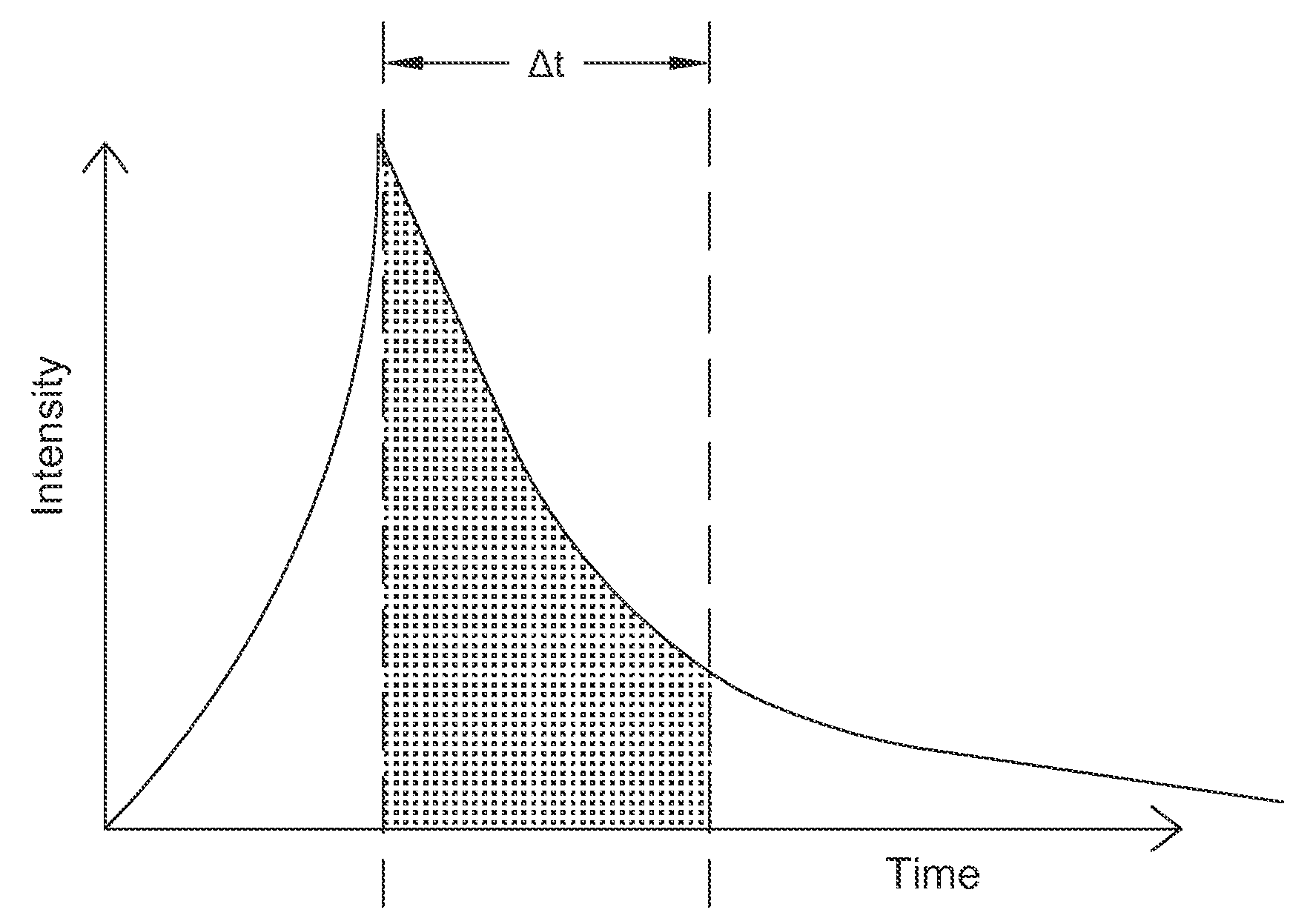
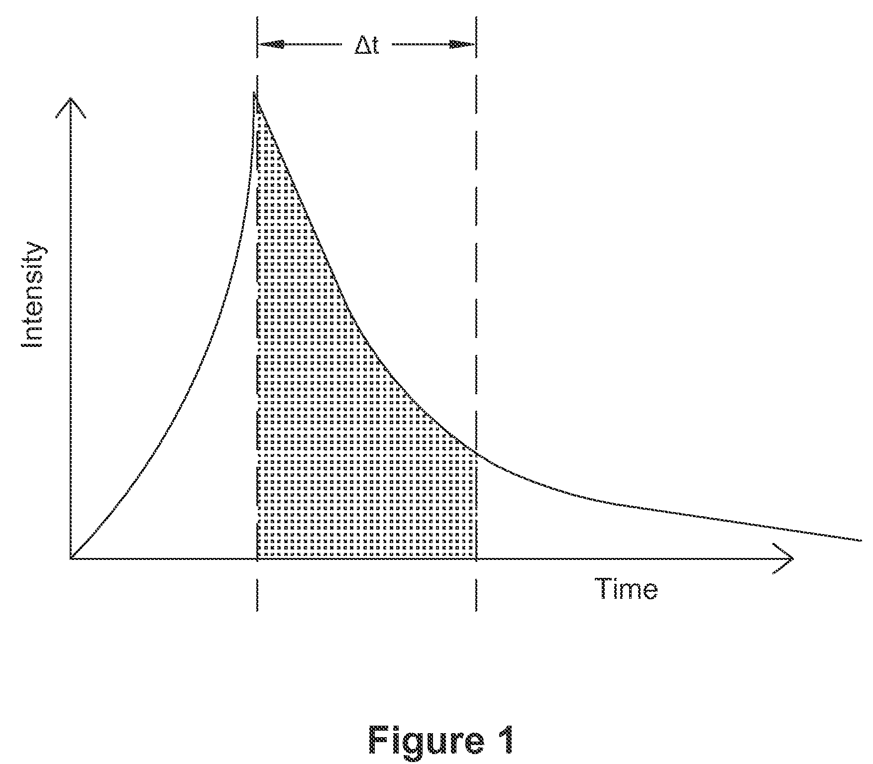
[0029]In one embodiment, a method of achieving higher signal-to-noise ratio (SNR) in a composite material dosimeter is disclosed. The method includes time-gating the OSL or RPL response emission and rejecting the unwanted background fluorescence irrespective of its source. This emission process is optimally stimulated through the use of a fast laser pulse, LED or a flash lamp—fast being less than the time-constant of the OSL (or RPL) emission process being targeted—applied to an exposed material. The emission signal of the exposed material is then amplified and measured at a fixed time window or interval on the order of a half-life of the decay constant of the material. This process can be repeated for hundreds to thousands of pulses or more. Since ultra-fast pulsed lasers, ...


PUM

PropertyMeasurementUnit
decay time constantaaaaaaaaaa
sizeaaaaaaaaaa
sizeaaaaaaaaaa

Abstract

A method of measuring luminescence of a material is disclosed. The method includes applying a light source to excite an exposed material. The method also includes amplifying an emission signal of the material. The method further includes measuring a luminescent emission at a fixed time window of about 10 picoseconds to about 10 nanoseconds. The luminescence may be radio photoluminescence (RPL) or optically stimulated luminescence (OSL).

Description

CROSS-REFERENCE TO RELATED APPLICATIONS[0001]This application claims priority from U.S. Provisional Patent Application Ser. No. 61 / 494,796 and entitled “METHOD FOR RED-SHIFTING THE OSL OUTPUT IN COMPOSITE OSL MATERIALS AND APPLICATIONS THEREOF, which is hereby incorporated by reference in its entirety for all purposes.STATEMENT REGARDING FEDERALLY SPONSORED RESEARCH OR DEVELOPMENT[0002]The invention was made with Government support under Contract DE-AC05-76RL01830, awarded by the U.S. Department of Energy. The Government has certain rights in the invention.TECHNICAL FIELD[0003]This invention relates to measuring luminescence of a material. More specifically, this invention relates to measuring luminescence of a material by applying a light source to excite a material and measuring emission at a fixed time window, which minimizes background noise not related to a luminescent response of the material.BACKGROUND OF THE INVENTION[0004]Optically stimulated luminescence (OSL) and radio ph...

Claims


Application Information

Patent Timeline
Patent Type & Authority Patents(United States)
IPC IPC(8): G01N21/64G01T1/10G21K5/00G01T1/105G01T1/11G01J1/58
CPCG01T1/11G01T1/10G01T1/105G01J1/58G01N21/64G21K5/00
Inventor MILLER, STEVEN D.
Owner BATTELLE MEMORIAL INST
Learn More