Multi-electrode chemiresistor

a chemiresistor and multi-electrode technology, applied in the field of multi-electrode chemiresistors, can solve the problems of conductivity becoming sensitive to parameters, reducing the sensitivity of chemiresistors, and complicating these methods

Inactive Publication Date: 2015-12-22
BRANDENBURGISCHE TECHN UNIV COTTBUS SENFTENBERG
View PDF3 Cites 1 Cited by
  • Summary
  • Abstract
  • Description
  • Claims
  • Application Information

AI Technical Summary

Benefits of technology

[0069]In another preferred embodiment, the detector component of the device is an optical device, especially a spectrophotometer or a spectrofluorometer. Another advantage of the invention is the electric control of the redox-state of the chemosensitive material and the preferred detection by optical spectroscopy. The detection is carried out either through reflection or transmission spectroscopy. The same configurations are also used for fluorescence detection. This allows the reliable and quick detection of for example a gas by the device.
[0070]It was surprising, that a redox-state of a chemosensitive material can be measured and regenerated also if the chemosensitive material is mounted onto an isolated gate layer. The chemosensitive material is preferably a conductive polymer. As isolated base materials like Si covered by SiO2, Al2O3, glass or polymer foils can be used. The materials should be electrically isolating and chemically resistant towards the analyte and other substances of the analyte matrix.
[0071]The terminology of the present description is mainly directed towards conducting polymers. The terms conducting polymer or chemosensitive material or chemosensitive film also relate however to any other red-ox active chemosensitive materials, for example different not-polymerized redox active materials in the form of molecules, nanoparticles, adsorbed or immobilized layers, modified and non-modified graphenes, fulerenes, carbon nanotubes, red-ox active non-conjugated oligo- and polymers. Furthermore, one can combine red-ox active non-chemosensitive compounds with chemosensitive compounds; this may be prepared as a mixture, adsorbed or immobilized layer or as defined chemical groups conjugated with redoxactive materials.FIGURES
[0072]The following figures and examples demonstrate the effect of the invention:
[0073]FIG. 1 Examples of configurations capable of measuring conductometric responses

Problems solved by technology

The measurements of electrical current between two or more electrodes on a substrate is the most practical method, however the low conductivity of the chemically sensitive films under conditions typical for bioanalytical measurements (neutral ph, low oxidation potential) can complicate these methods.
When the material is separated over the gap, larger gaps commonly lead to thicker polymer films and therefore to a loss of sensitivity.
The application of a constant voltage or a constant current in order to measure changes in conductivity of sensors based on chemiresistors leads to various problems.
Additionally, a high voltage through a chemically sensitive film leads to heating of the film, which leads to the conductivity becoming sensitive to parameters such as air- or liquid flow.
When the contact resistance is high, and in comparison with the polymer resistance shows only changes regarding the analytes, it can limit the sensitivity of the system.
However, these measurements are relatively slow because a broad frequency band must be covered.
On the other hand, 4-electrode measurements alone provide no information on the resistance of the contacts between film and metal.
Many processes lead to the detachment or displacement of the film from the contacts or to the formation of poor conducting contacts.
One disadvantage of these methods of measurement is that they do not allow controt of the redox-state of the polymer or of any other chemosensitive material.
However with highly specific polymer resistance this asymmetric configuration can lead to variation or deviation in the condition of the polymer close to the second electrode and therefore to heterogeneous polymer properties between the source and drain electrodes.
However in this case the ohmic voltage drop at a low polymer resistance can lead to deviation from the applied potential.
The application of simultaneous 2- and 4-point measurements demonstrates that the data which is obtained through the 2-electrode configuration may contain significant mistakes regarding the contact resistance, especially regarding high polymer conductivity.
However the relatively small capacity of the ionic double-layer can limit the charge of the polymer oxidation.
There are various problems with affinity sensors which are based on conductive polymers or other chemiresistive materials.
Firstly, desorption of an analyte can be very slow.
However this can lead to damages of the chemosensitive material and it is time intensive to bring the sensor to the correct working temperature.

Method used


Image

  • Multi-electrode chemiresistor
  • Multi-electrode chemiresistor
  • Multi-electrode chemiresistor

Examples


example 1

Preparation of the Electrode and Testing

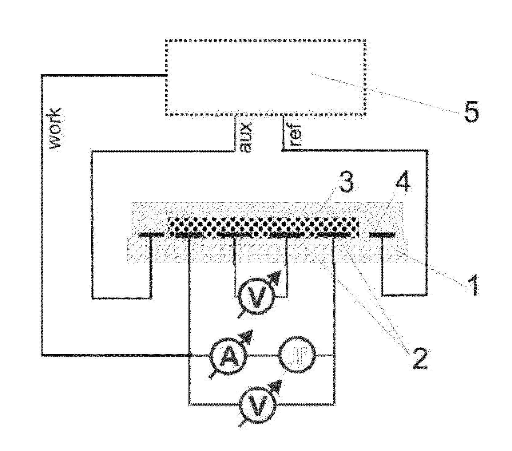
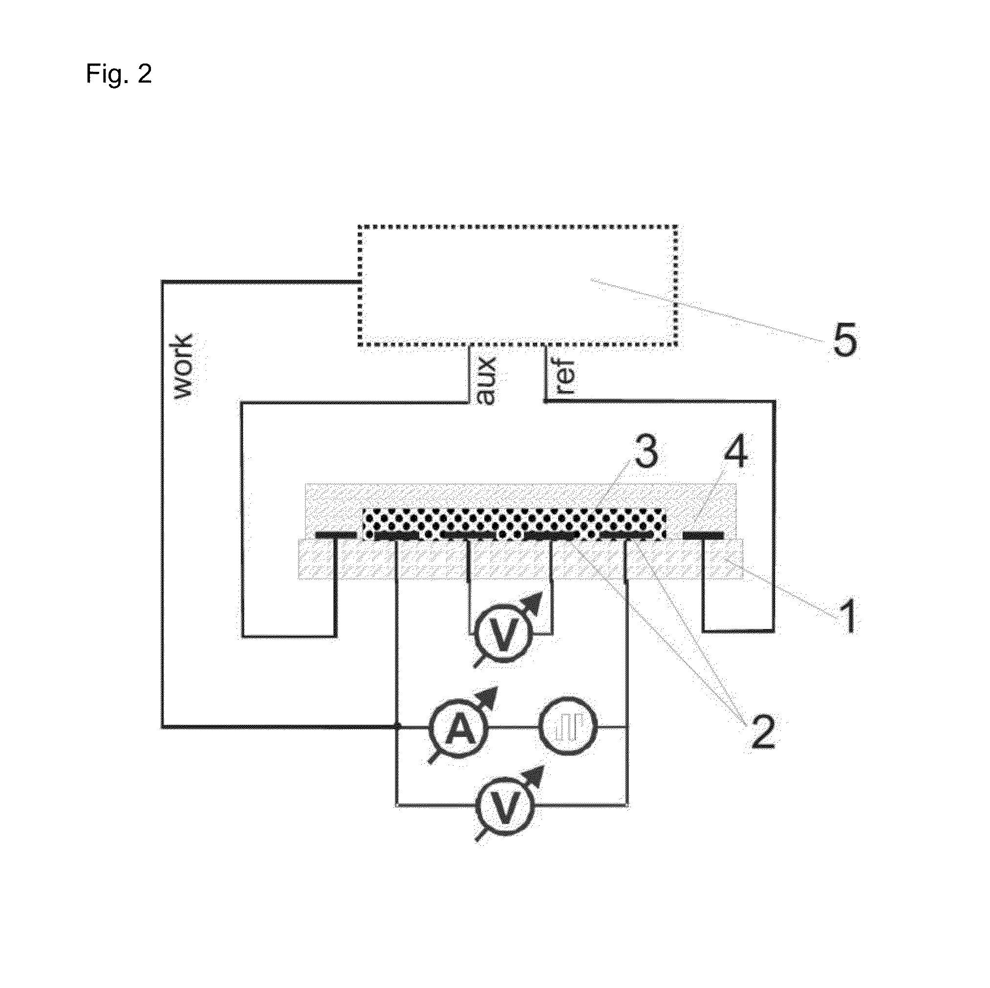
[0088]The electrodes presented in FIGS. 3 and 4 were used. The thickness of each electrode in this example was 150 nm of gold on a 15 nm adhesive layer of titan / wolfram applied on glass. This system (as described in Lange et al, J. Electroanal. Chem. 622, 246, 2008) was used in order to measure the 4- and 2-point resistance simultaneously and to calculate the contact and film resistances. A potentiostat “radiometer PGSTAT 201” was used in order to control the redox-state of the chemosensitive material.

[0089]The reference electrode was modified through electro-chemical reduction from silver (precipitation by −0.44 V vs CuSO4 from a solution of 0.1 M AgNO3 and 0.2 M EDTA which contains 1.5 M NH3). The electrode is thereafter covered with silver chloride (oxidation of the silver in 0.1 M HCl at 1 V vs Ag / AgCl). The auxiliary electrode and the work electrode are electro-chemically modified with polythiophene (polymerization at 1.35 V vs Ag / Ag+ fro...

example 2

Measurement of a Gas Analyte

[0090]The electrodes which were produced according to example 1 were used for the detection of highly diluted NO2. The results of the measurement are demonstrated in FIG. 6. The exposure of a sensor to NO2 containing air leads to an oxidation of the polythiophene into a dropping resistance. The spontaneous regeneration via flushing with air is very slow, whereby a short pulse with a cathodic voltage leads to the fast reduction of the chemosensitive material and leads to the regeneration of the sensor completely. The regeneration process can be carried out repeatedly (FIG. 6).

example 3

Preparation of the Sensor for Spectroscopy

[0091]The electrodes which are described in example 1 are used for the reflection spectroscopy experiments. The potential is controlled through the potentiostat “radiometer PGSTAT 201”. Changes in the optical spectrum after exposure to analytes are measured by the spectrophotometer with the assistance of fibre optics. The samples for the transmission spectroscopy are produced on the surface of indium-tin-oxide covered glass (FIG. 7). The indium-tin-oxide-layer is structured through the mechanical separation of the conductive layer. The measurement was carried out using a spectrophotometer.

[0092]For pH-measurements polyanilin or polypyrol is used as the sensitive layer. The measurements are carried out at constant potential.


PUM

PropertyMeasurementUnit
current/voltage dropaaaaaaaaaa
thickaaaaaaaaaa
frequencyaaaaaaaaaa

Abstract

The invention relates to “solid state” chemiresistor sensors with electric control of the affinity of a chemosensitive material. The configurations of the present invention enable the fast regeneration of the sensor after analyte binding, which therefore increases selectivity. In one embodiment the chemiresistor sensor is implemented as a multi-electrode chemiresistor, comprising 4 electrodes for the separate measurement of the resistance of the chemosensitive material and the contact resistance, and 2 further electrodes to control the redox state of the chemosensitive sensor material, thereby facilitating fast and effective regeneration of the sensor.

Description

CROSS-REFERENCE TO RELATED APPLICATIONS[0001]This is the U.S. national stage of International application PCT / EP2010 / 004406, filed Jul. 13, 2010 designating the United States and claiming priority to European application no. EP 09075311.2, filed Jul. 13, 2009.[0002]The invention relates to “solid state” chemiresistor sensors with electric control of the affinity of a chemosensitive material. The configurations of the present invention enable the fast regeneration of the sensor after analyte binding, which therefore increases selectivity. In one embodiment the chemiresistor sensor is implemented as a multi-electrode chemiresistor, comprising at least 2, preferably 4, electrodes for the separate measurement of the resistance of the chemosensitive material and the contact resistance, and at least 1, preferably 2, further electrodes to control the redox state of the chemosensitive sensor material, thereby facilitating fast and effective regeneration of the sensor.BACKGROUND OF THE INVEN...

Claims


Application Information

Patent Timeline
Patent Type & Authority Patents(United States)
IPC IPC(8): G01N27/26G01N27/12
CPCG01N27/126
Inventor MIRSKY, VLADIMIRLANGE, ULRICH
Owner BRANDENBURGISCHE TECHN UNIV COTTBUS SENFTENBERG
Why Eureka
Try Eureka