
Switching power supply device and battery charger including the same

a technology of switching power supply and battery charger, which is applied in the direction of electric variable regulation, process and machine control, instruments, etc., can solve problems such as system destruction, and achieve the effect of improving system efficiency and reducing spike voltag

Active Publication Date: 2016-01-19
HYUNDAI MOTOR CO LTD
View PDF17 Cites 4 Cited by
  • Summary
  • Abstract
  • Description
  • Claims
  • Application Information

AI Technical Summary

Benefits of technology

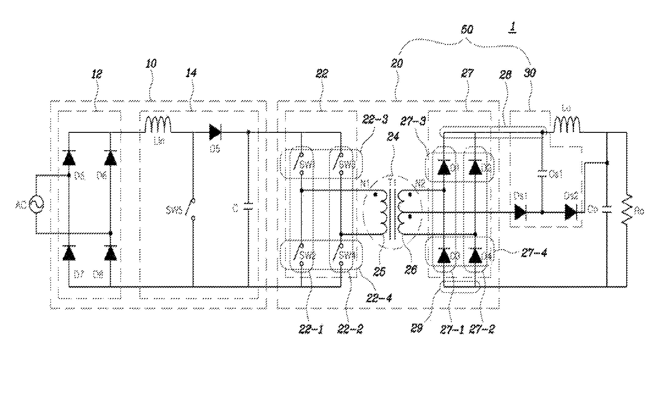
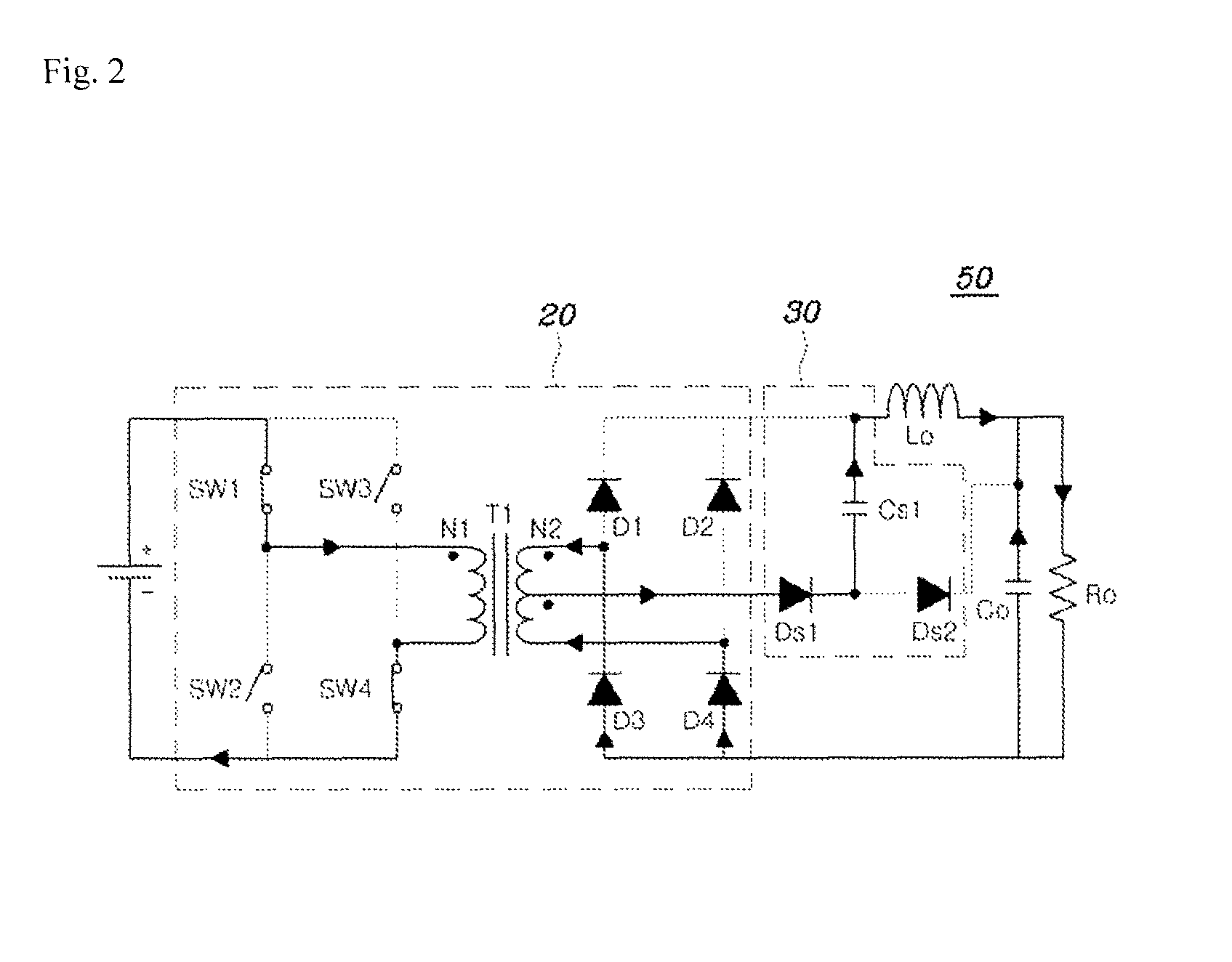
The invention is a device and method for driving it that helps reduce spike voltages at the output of a diode rectifier. It achieves this by reducing the voltage stored in a snubber capacitor and the current flowing through a snubber diode when a voltage is induced to the primary coil. The device also includes a feedback segment for current from the transformer, which enables zero voltage switching of the switching devices inside the DC / DC converter and improves efficiency of the system.

Problems solved by technology

Such a voltage spike may lead to destruction of a system.

Method used


Image

  • Switching power supply device and battery charger including the same
  • Switching power supply device and battery charger including the same
  • Switching power supply device and battery charger including the same

Examples


Embodiment Construction

[0027]Specific structural and functional descriptions of embodiments of the present invention disclosed herein are only for illustrative purposes of the embodiments of the present invention. The present invention may be embodied in many different forms without departing from the spirit and significant characteristics of the present invention. Therefore, the embodiments of the present invention are disclosed only for illustrative purposes and should not be construed as limiting the present invention.

[0028]Reference will now be made in detail to various embodiments of the present invention, specific examples of which are illustrated in the accompanying drawings and described below, since the embodiments of the present invention can be variously modified in many different forms. While the present invention will be described in conjunction with exemplary embodiments thereof, it is to be understood that the present description is not intended to limit the present invention to those exemp...


PUM


Abstract

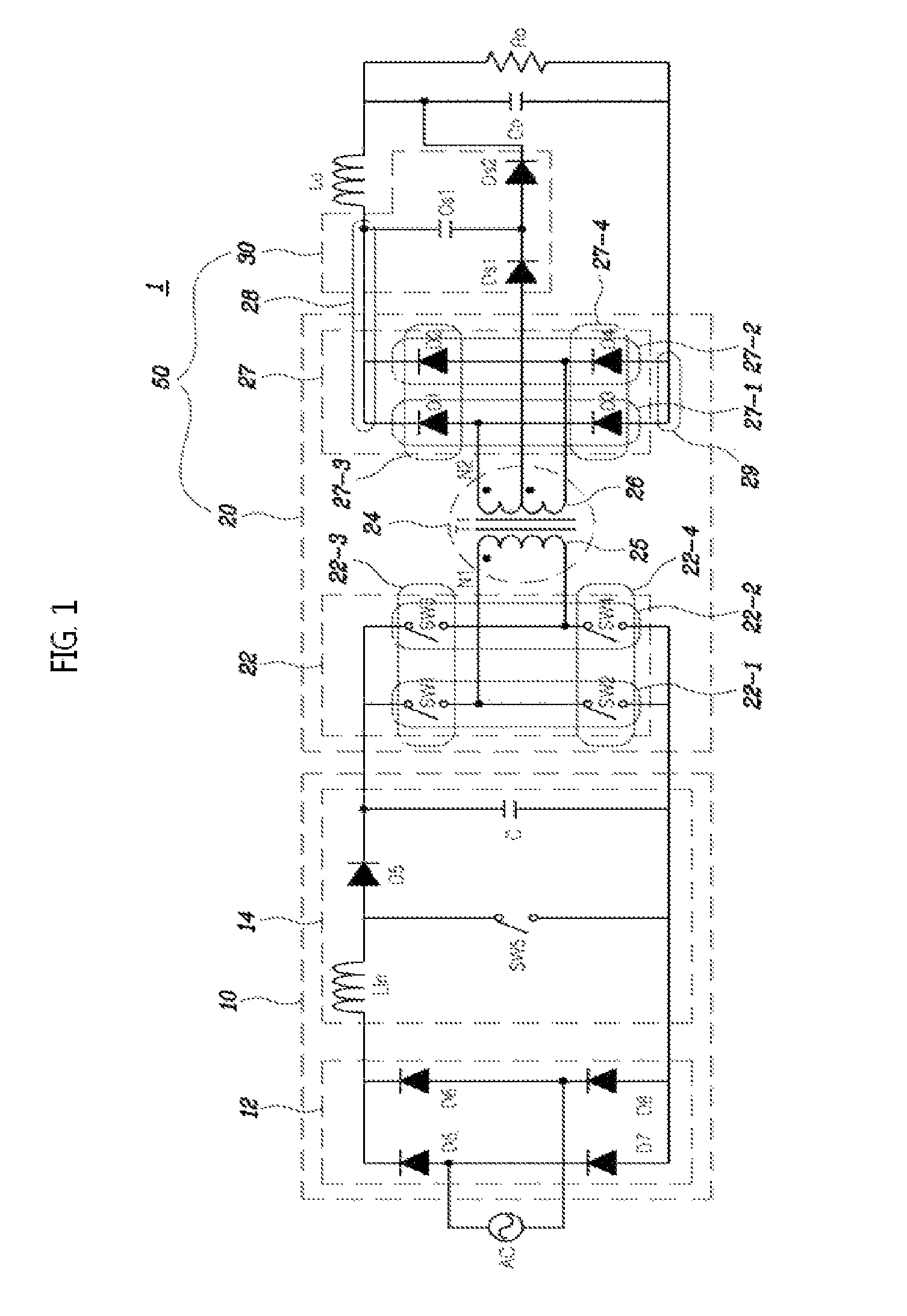
A switching power supply device includes a full-bridge circuit comprising a plurality of switching devices, a transformer comprising a primary coil and a secondary coil, the primary coil being connected to an output of the full-bridge circuit, and a DC / DC converter comprising a rectifier circuit. The rectifier circuit includes a plurality of diodes and is connected to the secondary coil to rectify a voltage outputted from the secondary coil. A snubber circuit includes a first snubber diode connected to an intermediate point of the secondary coil, a second snubber diode connected in series with the first snubber diode, the second snubber diode being connected to one end of an output capacitor, and a snubber capacitor connected between a node between the first and second snubber diodes and a positive side output of the rectifier circuit.

Description

CROSS-REFERENCE TO RELATED APPLICATION[0001]The present application claims priority to Korean Patent Application No. 10-2013-0120886 filed on Oct. 10, 2013, the entire contents of which is incorporated herein for all purposes by this reference.BACKGROUND OF THE INVENTION[0002]1. Technical Field[0003]The present disclosure relates, in general, to a switching power supply device and a battery charger including the same, and, more particularly, to a switching power supply device which can effectively reduce voltage spikes of a rectifier in a high-voltage output circuit, and a battery charger including the same.[0004]2. Description of the Related Art[0005]In switching power supply devices using a snubber capacitor, a leakage inductance component of a transformer may be interlocked with a parasitic capacitor of a diode rectifier device, thereby generating resonance or a voltage spike. Such a voltage spike may lead to destruction of a system.[0006]The foregoing is intended merely to aid i...

Claims


Application Information

Patent Timeline
Patent Type & Authority Patents(United States)
IPC IPC(8): H02J7/00H02M3/335H02M1/34
CPCH02M1/34H02M3/33569H02J7/0052H02M3/33546H02M2001/346H02J2007/0059Y02B70/1491H02M1/346H02M3/33573H02J2207/20H02J7/02Y02B40/00Y02B70/10H02J7/04H02M7/06H02J7/00
Inventor LEE, WOO YOUNGSONG, BYEONG SEOBLEE, DAE WOOYANG, JIN YOUNGKIM, JONG PILL
Owner HYUNDAI MOTOR CO LTD
Learn More