Honeycomb catalyst body

a honeycomb and catalyst technology, applied in the field of honeycomb catalyst bodies, can solve the problems of partition wall mechanical strength not being sufficiently obtained, partition wall breakage, pressure loss increase, etc., and achieve the effect of ensuring the strength of the honeycomb structure, reducing the initial pressure loss, and high mechanical strength

Active Publication Date: 2016-04-05
NGK INSULATORS LTD
View PDF20 Cites 8 Cited by
  • Summary
  • Abstract
  • Description
  • Claims
  • Application Information

AI Technical Summary

Benefits of technology

[0012]The present invention has been developed in view of problems of such conventional technologies. An object thereof is to provide a honeycomb catalyst body capable of containing in a limited space, having high mechanical strength, less pressure loss, and suitable purification performance.
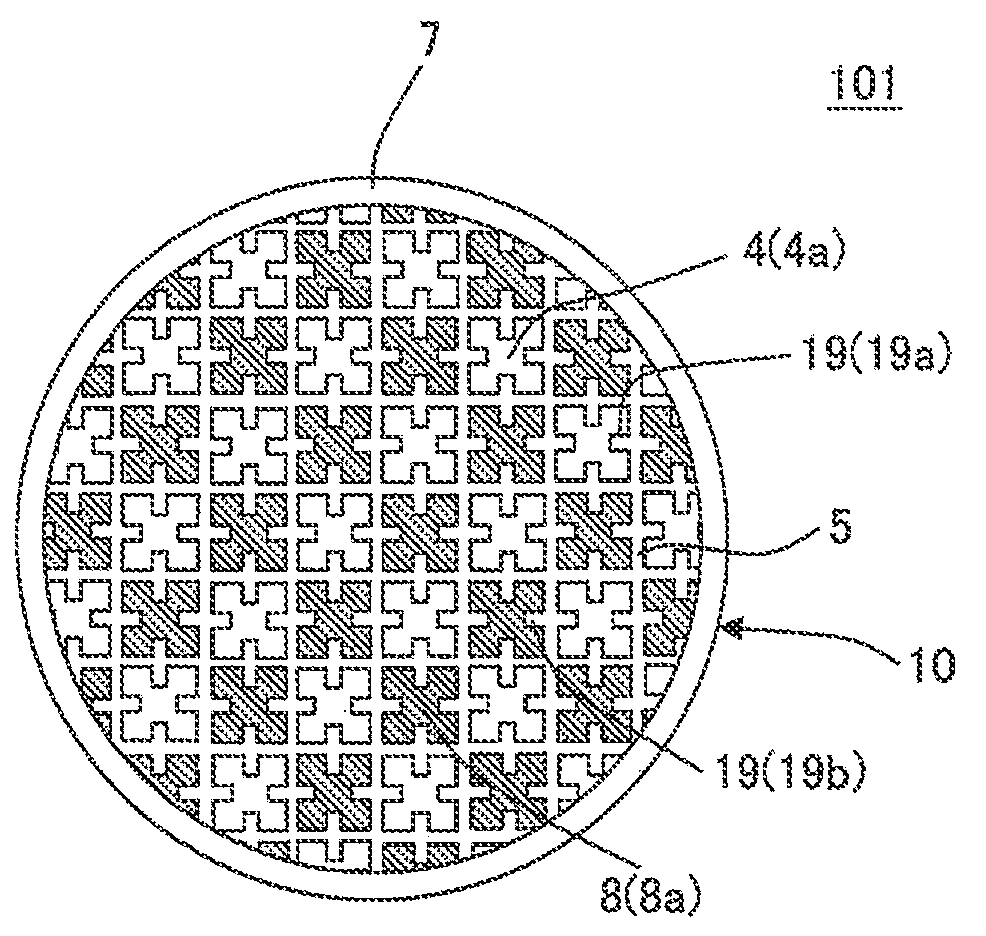
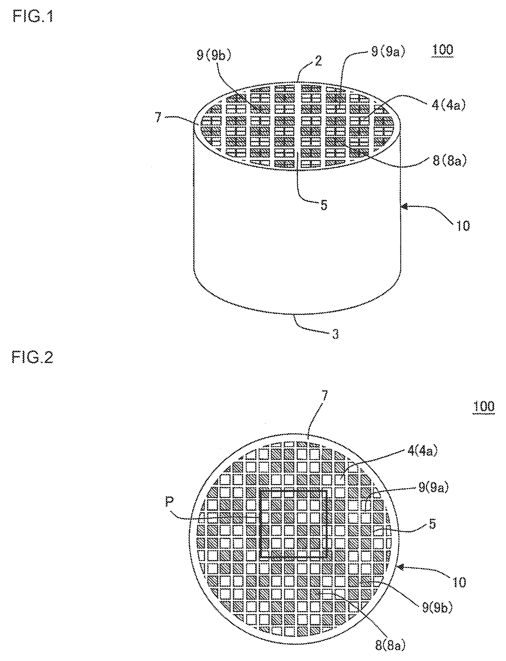
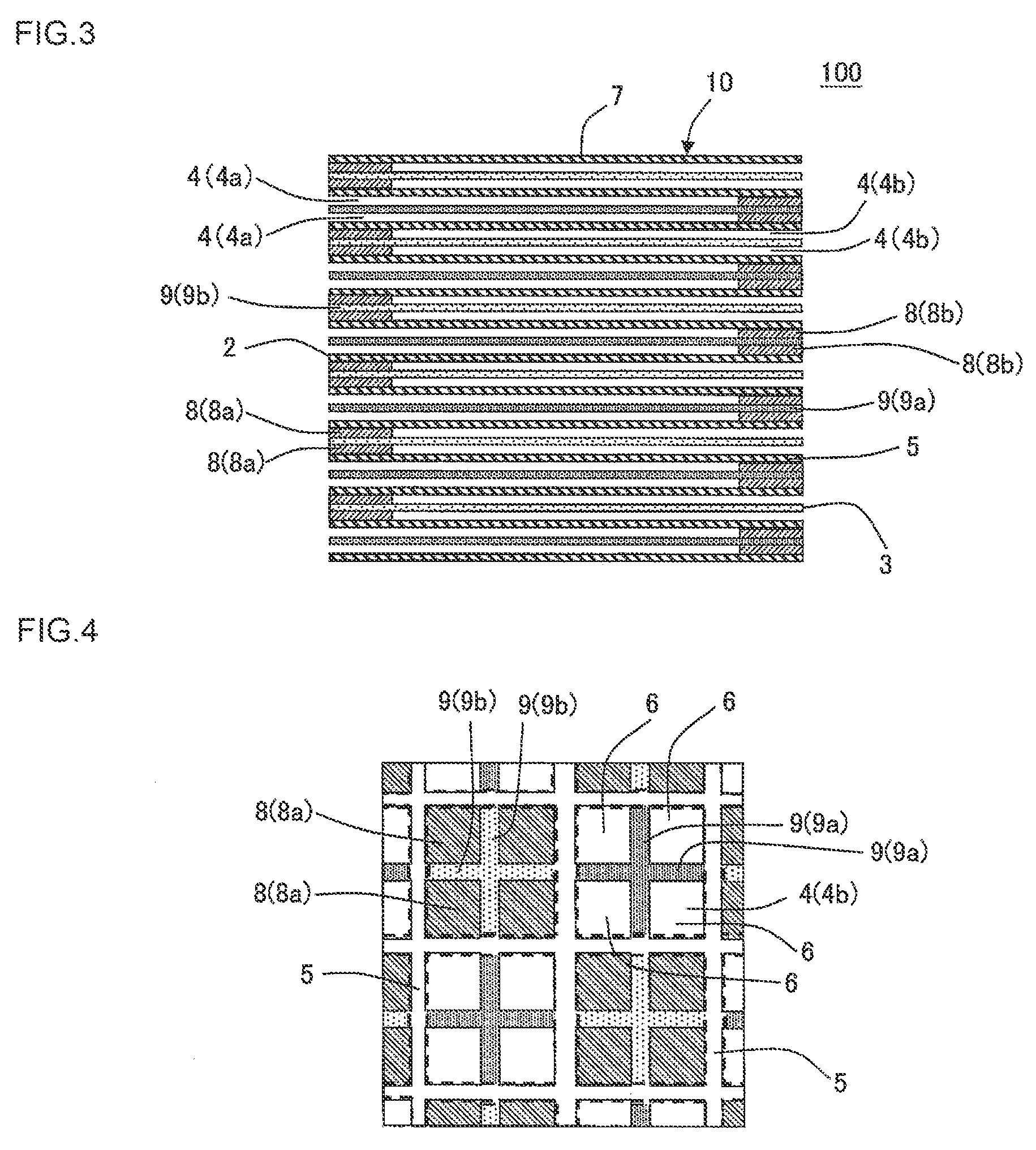
[0020]In a honeycomb catalyst body of the present invention, a selective reduction catalyst (SCR) is loaded onto projecting portions extending into inflow cells of a plugged honeycomb structure, and an ammonia slip preventing catalyst (ASC) is loaded onto projecting portions extending into outflow cells of the plugged honeycomb structure. Therefore, without using a plurality of honeycomb catalyst bodies (a honeycomb catalyst body loaded with the SCR and a honeycomb catalyst body loaded with the ASC), purification of harmful substances in an exhaust gas can suitably be performed by one honeycomb catalyst body. That is, the honeycomb catalyst body of the present invention is the one honeycomb catalyst body, but a purification performance thereof is suitable. In this way, when the honeycomb catalyst body of the present invention is used, the honeycomb catalyst body, which has heretofore been used plural, can be used only one, and thereby the honeycomb catalyst body can suitably be contained in a space even when a containing space is limited such as automobile. That is, when the honeycomb catalyst body of the present invention is used, the containing space of the honeycomb catalyst body may be small. Moreover, in the honeycomb catalyst body of the present invention, a porosity of each of partition walls of the plugged honeycomb structure is from 40 to 70%, and thereby the partition walls are comparatively dense. Therefore, the honeycomb catalyst body of the present invention has high mechanical strength. Moreover, in the honeycomb catalyst body of the present invention, a thickness of each of the projecting portions is from 30 to 140% of a thickness of each of the partition walls, and thereby it is possible to suppress an initial pressure loss lower while ensuring the strength of the plugged honeycomb structure. Furthermore, in the honeycomb catalyst body of the present invention, an amount of the catalyst loaded onto the partition walls in a cross section perpendicular to an extending direction of the cell is 40% or less of a total amount of the catalysts loaded onto the plugged honeycomb structure. Additionally, the amount of the catalyst to be loaded onto the partition walls is smaller than an amount of the catalyst to be loaded onto the projecting portions. Therefore, in the honeycomb catalyst body of the present invention, it is possible to suppress an increase of a pressure loss caused by loading a large amount of the catalyst onto the partition walls to clog or noticeably narrow pores in the partition walls. Furthermore, in the honeycomb catalyst body of the present invention, the amount of the catalyst to be loaded onto the partition walls is reduced to prevent the increase of the pressure loss, but instead, a larger amount of the catalyst is loaded onto the projecting portions than onto the partition walls, and thereby a catalyst performance is maintained and the purification performance is suitable.

Problems solved by technology

Therefore, there is a case where mechanical strength of the partition walls cannot sufficiently be obtained at the case of trying to prevent the increase of the pressure loss, and therefore the partition walls might be broken when a load is applied to the partition walls at canning.
Moreover, when the purification performance of the catalyst is ensured, i.e., when an amount of the loaded catalyst is large, pores to become through channels of an exhaust gas become narrow, and thereby the pressure loss may increase.

Method used


Image

  • Honeycomb catalyst body
  • Honeycomb catalyst body
  • Honeycomb catalyst body

Examples


example 1

[0091]As cordierite forming raw materials, alumina, aluminum hydroxide, kaolin, talc and silica were used. To 100 parts by mass of this cordierite forming raw material, 10 parts by mass of a pore former, 20 parts by mass of a dispersion medium, 1 part by mass of an organic binder and 0.5 part by mass of a dispersant were added, respectively, and the resultant were mixed and kneaded to prepare a kneaded material. As the dispersion medium, water was used, and as the pore former, cokes having an average particle diameter of 12 μm were used. As the organic binder, hydroxypropyl methylcellulose was used, and as the dispersant, ethylene glycol was used.

[0092]Next, the kneaded material was extruded by using a predetermined die, to prepare a honeycomb formed body having partition walls defining a plurality of cells extending through the honeycomb formed body from one end face to another end face, and projecting portions projecting so as to extend from this partition walls into cells and bei...

examples 2 to 6

[0124]The exhaust gas purifying devices were prepared in the same manner as Example 1 except that honeycomb catalyst bodies and the exhaust gas purifying devices satisfying conditions shown in Table 1 were prepared. Afterward, the respective prepared honeycomb catalyst bodies and exhaust gas purifying devices were evaluated in the same manner as in Example 1. The results are shown in Table 1, Table 2, and Table 5.


PUM

PropertyMeasurementUnit
porosityaaaaaaaaaa
pore diameteraaaaaaaaaa
thicknessaaaaaaaaaa

Abstract

A honeycomb catalyst body capable of containing in a limited space, having high mechanical strength, less pressure loss, and suitable purification performance is provided, and it includes a plugged honeycomb structure having porous partition walls defining cells, plugged portions, and porous projecting portions projecting so as to extend from the partition walls into the cells and being formed integrally with the partition walls; and catalysts loaded onto the projecting portions, wherein a porosity of the partition walls is 40 to 70%, thicknesses of the projecting portions is from 30 to 140% of thicknesses of the partition wall, an amount of the catalyst loaded onto the partition walls thereof is smaller than an amount of the catalyst loaded onto the projecting portions, one catalyst loaded onto projecting portions is a selective reduction catalyst, and another catalyst loaded onto projecting portions is an ammonia slip preventing catalyst.

Description

[0001]The present application is an application based on JP-2012-264747 filed on Dec. 3, 2012 with the Japanese Patent Office, the entire contents of which are incorporated herein by reference.BACKGROUND OF THE INVENTION[0002]1. Field of the Invention[0003]The present invention relates to a honeycomb catalyst body. More particularly, the present invention relates to a honeycomb catalyst body capable of containing in a limited space, having high mechanical strength, less pressure loss, and suitable purification performance.[0004]2. Background Art[0005]It has been demanded that harmful substances such as NOx in exhaust gases discharged from internal combustion engines such as an automobile engine, a construction machine engine and a stationary engine for industrial machine, the other burning devices and the like are purified and then discharged, in consideration of influences on the environment. Therefore, in order to purify this harmful substances, there has been used an exhaust gas ...

Claims


Application Information

Patent Timeline
Patent Type & Authority Patents(United States)
IPC IPC(8): B01D50/00B01J37/02F01N3/28B01J35/00C04B38/00B01J35/10B01J35/04C04B111/00
CPCF01N3/2828B01J35/002B01J35/006B01J35/04B01J35/10B01J35/1076B01J37/0215C04B38/0009C04B38/009C04B35/195C04B2111/0081B01J35/0006
Inventor AOKI, TAKASHI
Owner NGK INSULATORS LTD
Why Eureka
Try Eureka