
Wireless signal propagation apparatus

a wireless signal and apparatus technology, applied in the direction of substantially flat resonant elements, elongated active elements, resonant antennas, etc., can solve the problems of inability to communicate physically, physical inability, and difficulty in communicating directly through metal barriers, so as to achieve significant cost and time savings

Active Publication Date: 2016-04-05
ROLLS ROYCE PLC
View PDF24 Cites 4 Cited by
  • Summary
  • Abstract
  • Description
  • Claims
  • Application Information

AI Technical Summary

Benefits of technology

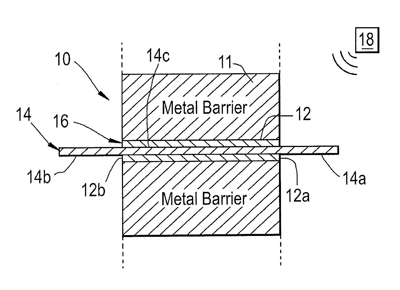
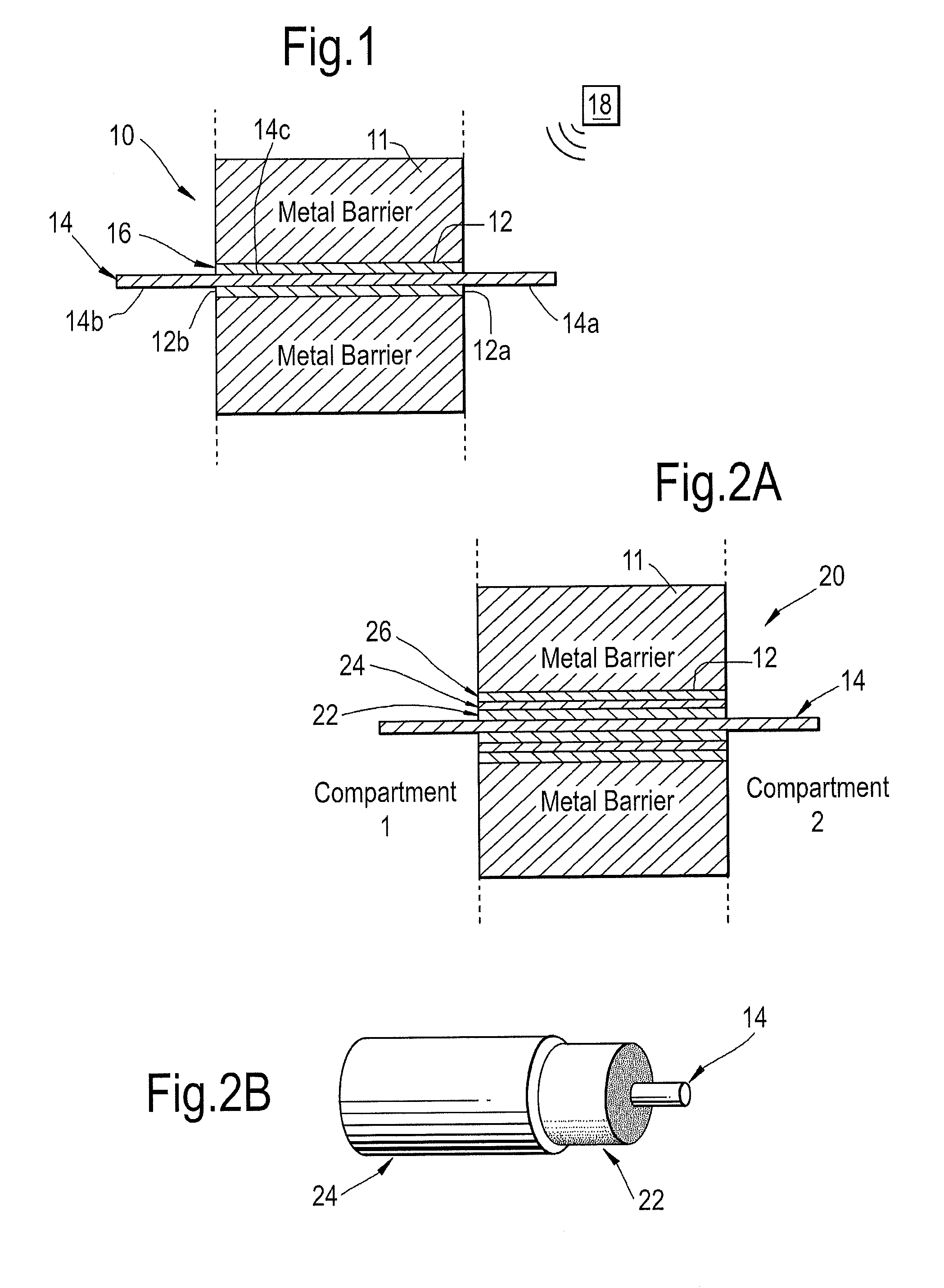
[0026]The invention may allow bridging of wireless communication signals between the interior and the exterior of an isolated metal compartment, or else between compartments separated by a metal barrier. The apparatus itself can be extremely small and unobtrusive with a diameter of, for example, 0.9 mm if using a 0.5 mm single core with 0.2 mm insulation layer. Thus the invention may allow a relatively small hole (i.e. a few mm's or less) to be provided in the barrier, whilst allowing for transmission of conventional wavelengths of wireless communication signals.
[0029]In one embodiment, the conductor member may comprise existing cabling (power, data, etc.), allowing it to be used as a re-radiating element (without interference to existing systems) allowing signals to be bridged between the interior and exterior of a compartment without the need to amend or introduce new cabling. This can allow fast introduction / retrofit of new control and monitoring functionality into systems with minimal installation cost and modification to the system.
[0031]The invention may have particular importance for the marine sector where limited time and access is available for installation. In oil-filled or radioactive environments the invention may provide significant cost and time savings as it eliminates the need to bore and seal new holes, normally required by conventional electrical cabling, allowing data to be transmitted from areas subject to adverse conditions.

Problems solved by technology

However it is known that wireless technologies face difficulties communicating directly through metal barriers.
Communication is physically impossible where there is no direct or indirect propagation path available between transmitter and receiver, such as when the two entities are located in separate, sealed metal compartments.
This is often not possible due to design restrictions, for example in enclosures that are required to contain fluid or to be sealed and / or pressurized in use.
Holes of such magnitude can also compromise the structural integrity of the barrier / wall being penetrated.
Furthermore, if one attempts to provide a blank hole in the metal barrier to join the airspace between the two different compartments, and thereby bridge the metal barrier, the diameter needed to accommodate wireless signals using RF and microwave frequencies (i.e. for industrial, scientific and / or medical uses) is typically also too large to provide a viable solution for many applications.
Having such ‘large’ holes will have negative implications in complex metal structures that may be sealed, watertight, pressurized and / or contain oil, etc. in use.
However, such techniques are inherently high-powered and only allow very low data rates.
They also suffer reliability issues due to susceptibility to noise and therefore remain substantially unusable for many applications, especially in and around metallic equipment and machinery that suffer from mechanical noises, vibration and other random noises.

Method used


Image

  • Wireless signal propagation apparatus
  • Wireless signal propagation apparatus
  • Wireless signal propagation apparatus

Examples


Embodiment Construction

[0043]There exist numerous examples of compartments or enclosures having walls or casing which are substantially impenetrable to, or else provide a significant barrier to, the passage of conventional wireless communications signals. Some examples of such scenarios include aeronautical or automotive engine or propulsion compartments, such as gearboxes, thrusters (e.g. azimuth thrusters), fuel tanks or the like, but may also include other storage tanks, piping or enclosures for machinery or people. For example any road, rail or aerospace or marine transportation typically involves metal enclosures such as vessel compartments (e.g. spaced by bulkheads), goods containers or the like. Further examples may include pipes, such as oil and gas pipelines; industrial pumping equipment; clean rooms; security enclosures; nuclear containment vessels, amongst others.

[0044]The invention provides apparatus for bridging the communications signals between the interior and exterior of any such enclosur...


PUM


Abstract

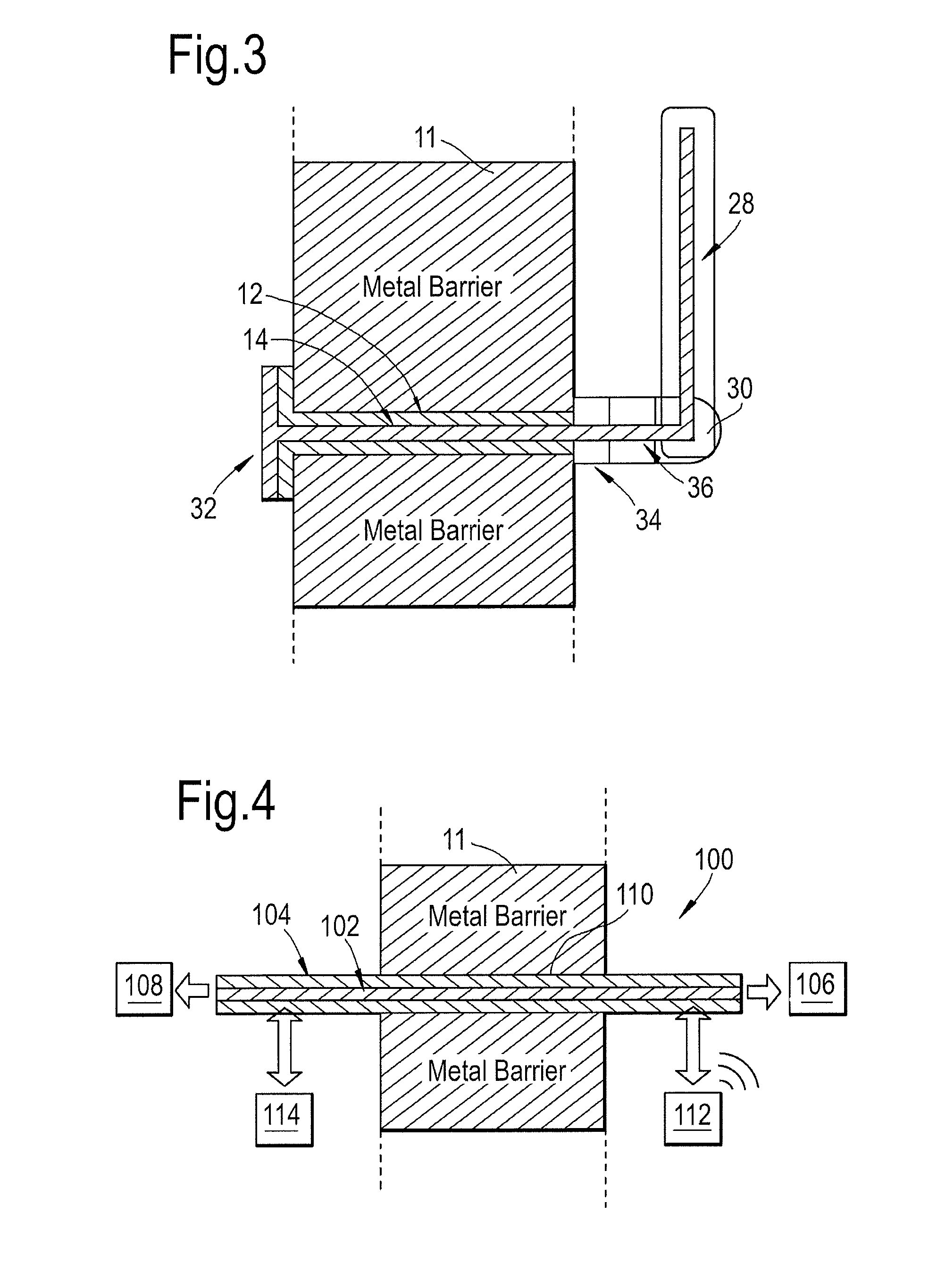
There is provided apparatus for propagation of a wireless signal through a barrier comprising a first antenna for location on a first side of the barrier, a second antenna for location on a second side of the barrier and a waveguide. The waveguide comprises a conducting member passing through the barrier between the first and second sides. The conducting member is held within an insulator sleeve such that it is spaced from a surrounding metal wall of the waveguide. A wireless signal received by the waveguide on the first side of the barrier is transmitted through the barrier by Transverse Electro-Magnetic (TEM) mode propagation along the waveguide is re-radiated on the second side.

Description

BACKGROUND OF THE INVENTION[0001]The present invention relates to apparatus for wireless signal propagation and, more particularly, apparatus for allowing wireless signal propagation through walls.[0002]Wireless communication systems, based on radio frequency (RF) or microwave frequency technologies, are becoming increasingly popular in replacing conventional wired systems, for example in machine monitoring, control and automation systems. Wireless signals have the ability to penetrate various mediums depending on their dielectric properties.[0003]However it is known that wireless technologies face difficulties communicating directly through metal barriers. Under conditions where a direct line-of-sight between a transmitter and a receiver is inhibited by a metal barrier, transmission of a wireless signal typically relies on indirect propagation paths or, so-called, ‘scatter’ wherein signals are reflected off the surfaces of other mediums to reach the desired receiver.[0004]Communica...

Claims


Application Information

Patent Timeline
Patent Type & Authority Patents(United States)
IPC IPC(8): H04B7/145H01Q1/00H01Q9/04H01Q9/30H01Q3/06
CPCH04B7/145H01Q1/007H01Q3/06H01Q9/0407H01Q9/30
Inventor ONG, MAX CHIEN YEETHOMPSON, HAYDN ASHLEYEDWARDS, HUW LLEWELYN
Owner ROLLS ROYCE PLC
Learn More