Induction vehicle detection and identification system, induction license plate, and induction reader

a technology of induction vehicle and identification system, which is applied in the direction of individual entry/exit register, instrument, electromagnetic radiation sensing, etc., can solve the problems of reduced range and reliability, over-complexity, complete signal loss, etc., and achieve safe and reliable system operation and simplify the effect of the system

Active Publication Date: 2016-04-19
MATSUR
View PDF2 Cites 4 Cited by
  • Summary
  • Abstract
  • Description
  • Claims
  • Application Information

AI Technical Summary

Benefits of technology

[0029]Accordingly, the objective of the invention is to to simplify the system and to make it single-band. Another objective is to use a magnetic frame placed under the roadway instead of antenna fixtures over the road or at the roadside. In addition, there is an objective to provide safe and reliable functioning of the system to detect and identify fast-moving vehicles.
[0054]Accordingly, the objective of the invention is to to make the system autonomous and operable in passive mode, as well as to increase its reliability by decreasing its operating frequency range and integrating it into induction HF-band vehicle identification system of ultra-long range.
[0072]Accordingly, the objective of the invention is to to provide for identification of moving vehicles and increase reliability of the system.

Problems solved by technology

1. It is overly complex, since it requires using both HF and UHF bands to connect electronic identification devices mounted on vehicles and electronic reading devices.
2. UHF-band antennas can't be placed under the roadway because of high wave attenuation. They can't be placed on the roadway as well, because certain weather conditions, such as rain, mud, snow and ice, decrease their range and reliability by increasing wave attenuation and distorting the orientation diagram of their electromagnetic fields. A UHF-band RFID-system comprising a transponder, an antenna and a reader is operable only under conditions of radio visibility, while large objects, such as vehicles or houses, whose size is proportionate to the wavelength, can cause a complete loss of signal, as they shield electromagnetic waves, or can cause interference leading to signal distortion.
However, such constructions do not solve the problem of interference for UHF band, which leads to connection failures and decreases reliability of the system.
Interference also makes it difficult to locate the vehicle on the road.
Moreover, any construction over the road or at the roadside affects the architectural look of the site.
Such range is insufficient for identification of fast-moving objects, even those equipped with transponders, because the time required to read identification data exceeds the time a vehicle with transponder needs to pass through the antenna range.
Even if positioned across the road, this antenna won't still be able to cover the entire lane.
4. Such systems have a very short range, and the sizes of vehicles can vary within meters, thus if the antenna is placed over the road or at the roadside, it can't provide reliable vehicle detection.
Moreover, any constructions over the road or at the roadside affect the architectural look of the site and compromise traffic safety.
It is thus impossible to tune the system properly, which is why it can't function as needed.
These disadvantages thus limit the application of this solution.
The problem of this approach is that it is impossible to make the license plate autonomous, since its antenna requires an extra connection.
Such connections pose difficulties when mounting the plate, decrease its reliability, lead to signal losses, and make it impossible to operate in a passive mode.
Another problem is the need to excite the transmitter, which is already rather powerful, since a separate antenna unit requires high-frequency operation (in this case, 915 MHz).
At such frequencies, there is high signal attenuation, and thus it is difficult, or even impossible, for the license plate to operate in passive mode in radio-frequency communication.
Moreover, if a high carrier frequency is used, its wavelength can be proportionate to the size of the license plate, and thus it is prone to negative effects of multiple reflections and shadowing caused by nearby objects (e.g., other vehicles).
Multiple reflections distort the antenna orientation diagram, which makes it difficult, or even impossible, to detect and locate the plate, thus decreasing its reliability when interacting with vehicle identification systems.
These disadvantages thus limit the application of the device.
When a vehicle enters its range, its inductive impedance is disturbed.
1) it can't identify vehicles, since it doesn't comprise any means of signal decoding;
2) its reliability is low, as it can register two vehicles moving closely to each other as one vehicle, or there can be errors in registering oversized vehicles;
3) there is a high chance for the device to miss a small-sized vehicle;
4) the device can malfunction because of a sudden change in weather conditions;
5) the induction frame is in no way protected from mechanical impact of moving vehicles; it is thus prone to breakdowns and has a low durability.
These disadvantages thus limit reliability and application of the device.

Method used


Image

  • Induction vehicle detection and identification system, induction license plate, and induction reader
  • Induction vehicle detection and identification system, induction license plate, and induction reader
  • Induction vehicle detection and identification system, induction license plate, and induction reader

Examples


Embodiment Construction

[0098]Reference will now be made in detail to the embodiments of the present invention, examples of which are illustrated in the accompanying drawings.

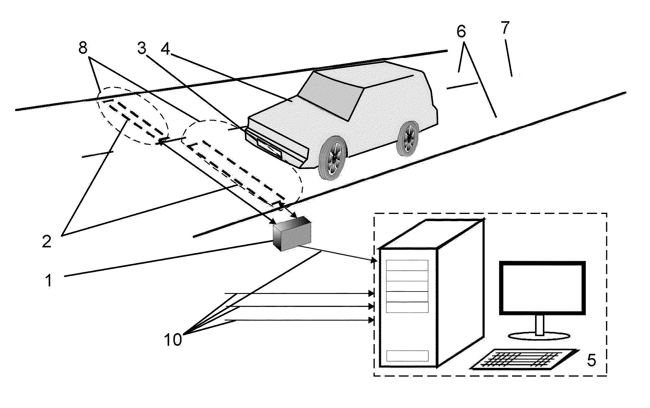
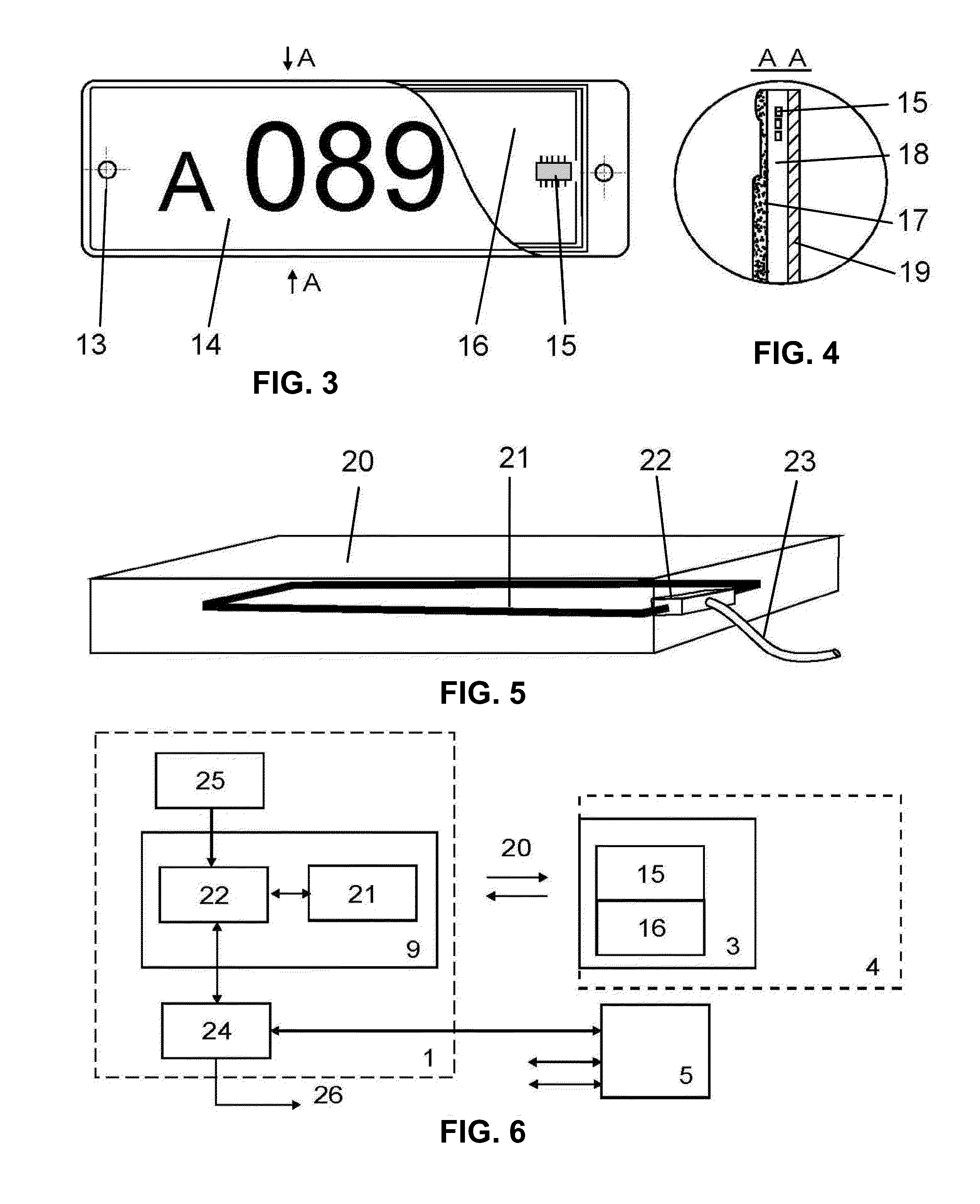
[0099]An induction vehicle detection and identification system comprises:[0100]an electronic vehicle identification device with a magnetic frame;[0101]a microchip with non-volatile memory for storing identification data of a vehicle with capacity of at least 64 bit;[0102]a reader to read data from electronic vehicle identification devices.

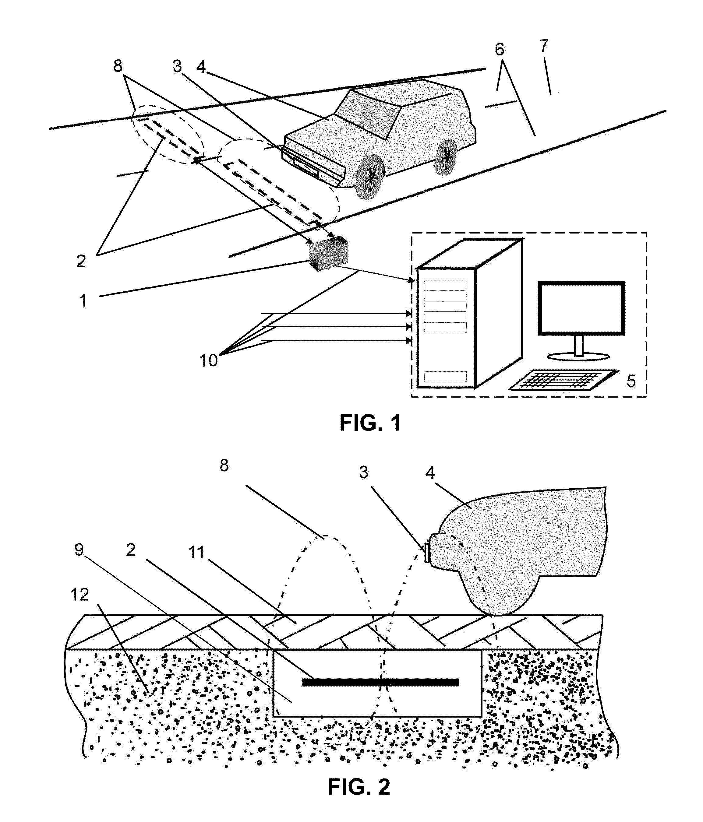
[0103]An electronic vehicle identification device is integrated into the license plate, thus making up an induction license plate mounted at the same place as a regular one.

[0104]The front side of an induction license plate is covered with identification data plate number for visual recognition.

[0105]The reader is equipped with a magnetic frame placed under the roadway up to 1 m deep. It can read information from the lane above. The frame is connected to a reader's generator, which feeds an alternati...


PUM


Abstract

An induction vehicle detection and identification system comprising electronic identification devices with electronic memory, mounted on vehicles, and a reader capable of reading and / or writing data obtained from devices in HF-band. Devices have a non-volatile memory and are integrated into the vehicle's license plate. The reader combined with a magnetic frame is in a dielectric casing, which is mounted under the roadway. It generates an alternating magnetic field, which determines the detection and identification range. Minimum time the reader requires to read discrete responses generated by electronic identification devices and to identify the vehicle is less than 25 ms. The identification devices and the reader exchange data at the rate of 1 Kbit / sec or higher, and provide data encoding and decoding, as well as data access restriction.

Description

CROSS-REFERENCE TO RELATED APPLICATIONS[0001]This application is a US National Phase of PCT Application No. PCT / RU2013 / 000096, filed on Feb. 11, 2013, which claims priority to RU 2012148736, filed on Nov. 16, 2012, which are all incorporated by reference herein in their entirety.BACKGROUND OF THE INVENTION[0002]1. Field of the Invention[0003]The present invention relates to traffic control and registration by means of vehicle identification.[0004]2. Background of the Related Art[0005]A conventional approach to traffic control is to use an automated vehicle identification system, comprising electronic identification devices mounted on vehicles and electronic reading and writing devices, both equipped with an induction transmitter and receiver. Electronic identification devices also include: at least one HF-band transmitter with range of 10-90 cm, at least one UHF-band transmitter with range of 300-1000 cm, and an electronic memory unit (see US20120056725).[0006]This system has a numb...

Claims


Application Information

Patent Timeline
Patent Type & Authority Patents(United States)
IPC IPC(8): G06K5/00G07C9/00G06K19/073G06K19/077G06F21/62G08G1/017G08G1/042G06K7/10B60R13/10
CPCG06K7/10267B60R13/10G06F21/6218G06K7/10336G06K19/07309G06K19/07783G07C9/00007G08G1/017G08G1/042G07C9/20
Inventor MATSUR
Owner MATSUR
Why Eureka
Try Eureka