Method for accelerated fermentation and device for mixing a tank content

a technology of accelerated fermentation and tank content, which is applied in the field of accelerated fermentation in a fermentation tank, can solve the problems of low time-saving, method limitation by the physiology of yeast, and method without significant industrial meaning

Inactive Publication Date: 2016-05-10
GEA BREWERY SYST HUPPMANN TUCHENHAGEN
View PDF40 Cites 4 Cited by
  • Summary
  • Abstract
  • Description
  • Claims
  • Application Information

AI Technical Summary

Benefits of technology

[0027]Due to the improved convective current in the tank, the yeast cells can stay in suspension for a longer time, but also already sedimented yeast cells can, at least partially, be brought into suspension again.
[0028]In a preferred embodiment of the method according to the invention, the mixing member is arranged within the tank cone at a height (L) of 375 mm-1650 mm, preferably of 400 mm-1500 mm, between the bottom edge of the connection flange and the bottom edge of the mixing member. In this manner, the hydraulic decoupling of the suction area of the pump and the suction area of the injector or the mixing member, respectively, can be designed more efficiently.
[0035]Preferably, the drive volume flow (M1) is 6 m3 / h-50 m3 / h, further preferred 8 m3 / h-41 m3 / h. In practice, thus, for example, a drive volume flow (M1) of only about 8 m3 / h results for an average-sized tank (2660 hl useable volume) for 8 h circulation time. Even if a very large tank (10000 hl useable volume) and a somewhat faster recirculation pumping time of 6 h is assumed, only a drive volume flow of about 41 m3 / h is achieved. These values are significantly lower than the values known from the prior art. In this way, on the one hand, significant energy saving can be achieved at the pump drive, whereby, at the same time, the yeast cells are exposed to a lower shear stress by circulation pumping. On the other hand, very good circulation- or mixing-times, respectively, can be achieved nevertheless. A further advantage of the comparably low drive volume flows lies in that no devices for the reduction of froth or froth alerting sensors, as they are commonly used in the prior art, are necessary any more, since, due to the lower drive volume flows, there is no longer a risk of an increased froth generation. Furthermore, due to the increased homogeneity of the tank content, a generation of “CO2 nests” (increased CO2 concentration at specific locations in the tank) is avoided in the product. From these “CO2 nests”, often the disadvantageous froth-over of the tank content is generated. It has to be mentioned as a further advantage that in classic cylindro-conical fermentation tanks, commonly, a riser space of about 20-25% of the gross volume has to be maintained during the fermentation, so that a possible froth formation does not lead to an overflow of the tank. With the aforementioned measures, this riser space can be possibly reduced and thus, the useable volume of the tank can be increased. This is an additional utilization benefit for the brewery, since herewith both, the fermentation tank capacity and the output can be increased without additional tanks—and without the corresponding high investments.
[0037]In still another preferred embodiment of the method according to the invention, in step b), the drive fluid (M1) that is now pumped by the circulation pump via the second circulation pipe is injected into the mixing member by means of a drive head, wherein the drive fluid (M1) is mixed with further fermentation fluid (M2) that is sucked by means of the underpressure generated by the injection of the drive fluid (M1) via one or more inlet openings of the mixing member directly inside the mixing member, to a mixed jet (M12) that flows upwards through the mixing member; and wherein, in step c), the mixed jet (M12) that is directed upwards leaves through an outlet opening of the mixing member, so that the yeast cells stay in suspension for a longer time by the so improved convective current in the tank. Thereby, a more gentle treatment of the yeast is ensured and it is possible to use pumps with lower power.
[0039]In a preferred embodiment of the device according to the invention, the mixing member is arranged within the tank cone at height (L) of 375 mm-1650 mm, preferably of 400 mm-1500 mm between the bottom edge of the connection flange and the bottom edge of the mixing member. In this manner, in turn the hydraulic decoupling of the suction area of the pump and the suction area of the injector and respectively of the mixing member can be designed in an even more effective manner.

Problems solved by technology

Thus, the variation of parameters is limited to narrow borders by the physiology of the yeast, and the achievable savings in time are low.
But this method is limited by the physiology of the yeast.
However these methods do not have a significant industrial meaning due to the possible hygienic risks and some unsolved problems in the field of biomass-handling.
However, this method requires an additional use of carbon dioxide gas.
Due to the design of the target jet cleaner very high loss of pressure is caused.
Moreover, the mixing effects that are caused by the target jet cleaner is insofar problematic, since the natural convective current is disturbed by the jet impact.
Therefore, a current is generated in the tank, which causes the mixing of the tank content.
However, for the known injectors, the mixing effect is low and strong pumps are needed to circulate the entire tank content.
However, this effects that an insufficient suction stream is generated at the injector, since the pressure at the lateral openings of the injector is too low and thus, not enough fluid can be sucked in.
The area in which the suction stream S and the drive stream T are generated from the convective stream K is herein so narrow that at this location, very high current speeds come up, by which the dynamic pressure at this location becomes so small that the “suction pressure” of the injector is not able to generate any substantial suction current.
A higher arrangement of the injector inside the tank cone was declined up to now, because there was the fear that hereby, a too low yeast cell concentration would be sucked by the injector.

Method used


Image

  • Method for accelerated fermentation and device for mixing a tank content
  • Method for accelerated fermentation and device for mixing a tank content
  • Method for accelerated fermentation and device for mixing a tank content

Examples


Embodiment Construction

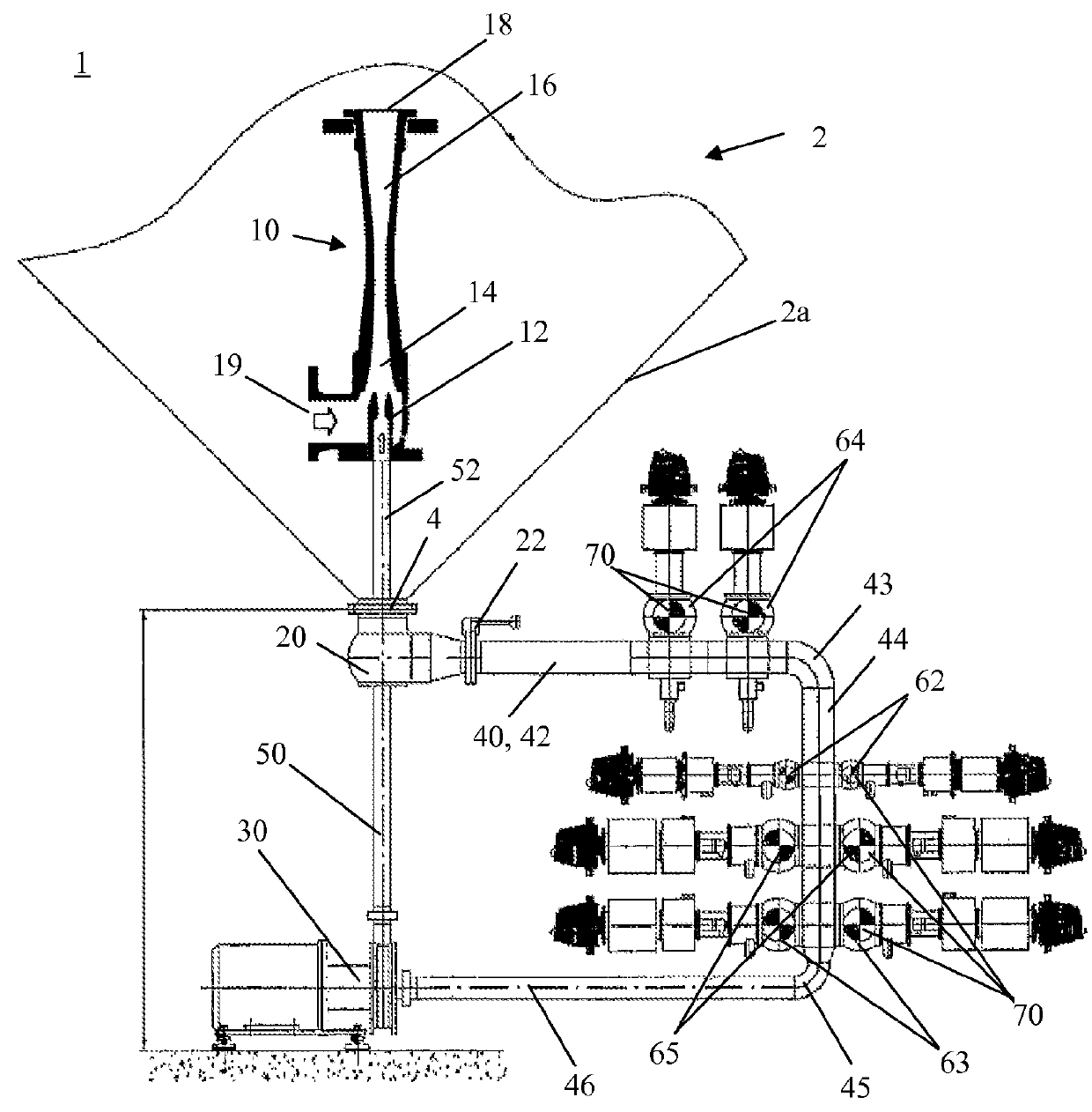
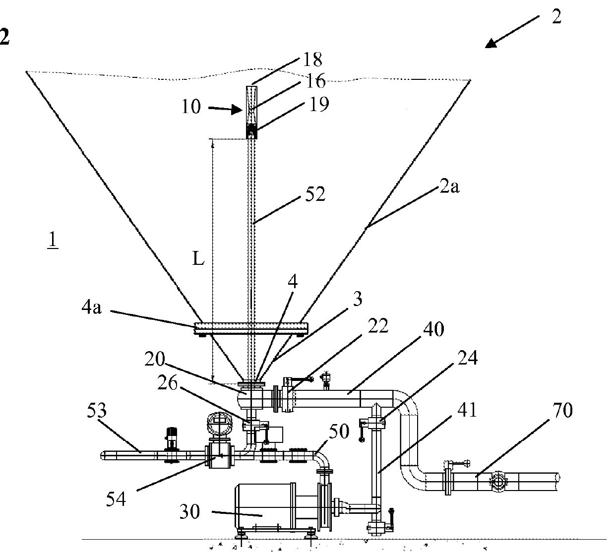
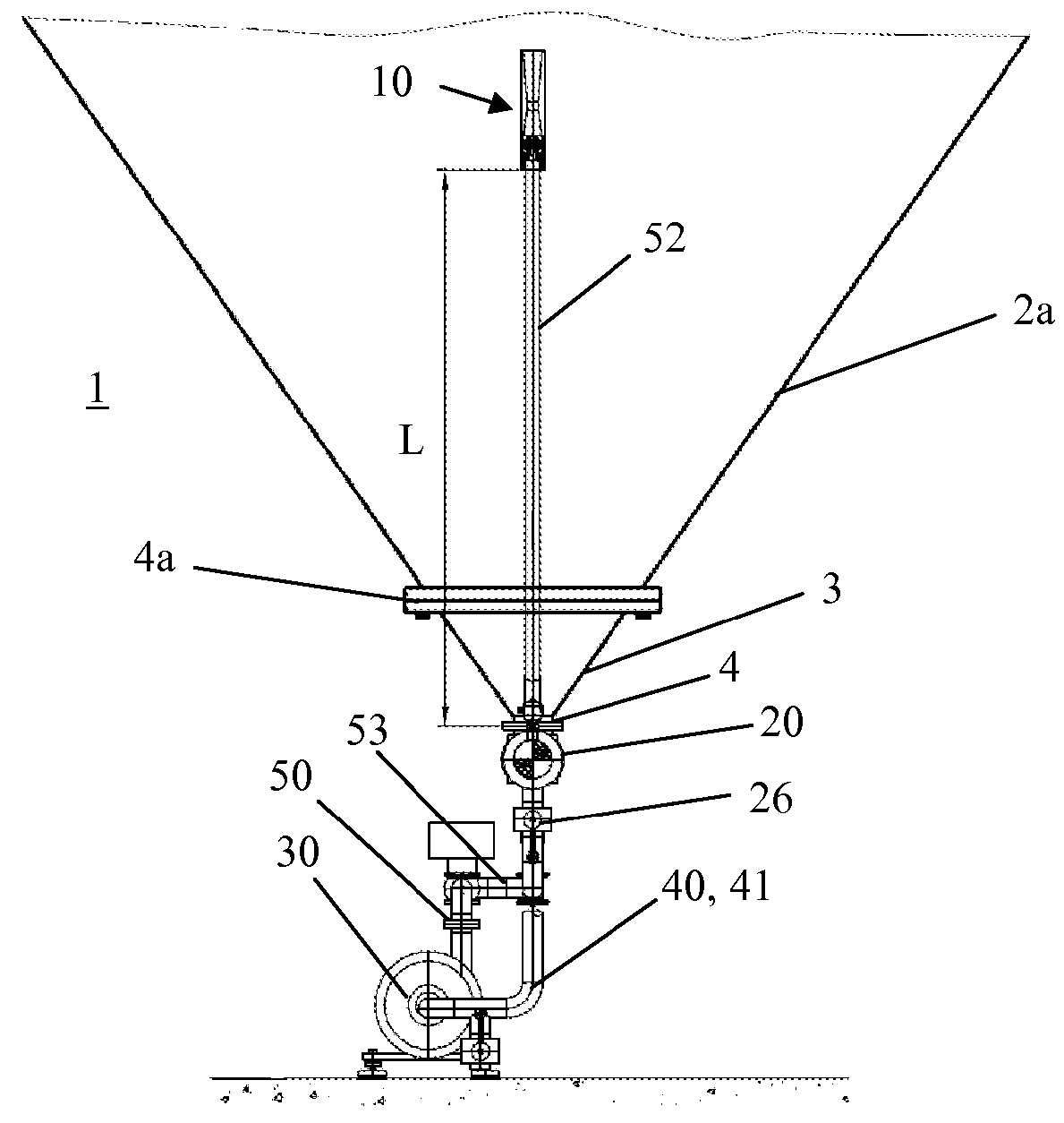
[0049]In the following, preferred embodiments of a device according to the invention to carry out the method according to the invention is described in detail. Particular features of an embodiment can be combined with features of other embodiments. In all embodiments, the same reference signs were used for corresponding features.

[0050]FIGS. 1-3 show schematic side and front views, respectively, of a device 1 according to the invention to carry out the method according to the invention, wherein FIG. 1 shows a first embodiment and FIGS. 2 and 3 show a second embodiment. In these figures, the bottom tank cone of a tank 2 is schematically shown. The tank 2 is, for example, a cylindro-conical tank (CCT) of a brewery construction, in particular a fermentation tank (CCFT).

[0051]As shown, a hollow-part-shaped inlet 20 is connected to a connection flange 4 at the lower end of the tank cone 2a (FIG. 1) and of the cone-man-hole 3 (FIGS. 2 and 3), respectively, so that fluid, or another medium,...


PUM

PropertyMeasurementUnit
heightaaaaaaaaaa
heightaaaaaaaaaa
heightaaaaaaaaaa

Abstract

The present invention relates to a method for an accelerated fermentation in a fermentation tank 2 with at least a tank cone 2a and a connection flange 4, in particular for beer production. The method comprises the steps: a) sucking in of fermentation fluid M1 from the tank 2 via a first circulation pipe 40 by means of a circulation pump 30; b) inducing of the drive fluid M1 that is now pumped by the circulation pump 30 via a second circulation pipe 50 in a mixing member 10 that is arranged within the tank cone 2a at a height L of 350 mm-1800 mm between the bottom edge of the connection flange 4 and the bottom edge of the mixing member 10; and c) generating of a jet directed upwards and exiting through an outlet opening 18 of the mixing member 10, so that the yeast cells stay for a longer time in suspension in the tank 2 by means of an in such a way improved convective current. The invention relates moreover to a corresponding device.

Description

1. TECHNICAL FIELD[0001]The invention relates to a method for the accelerated fermentation in a fermentation tank, in particular in beer-production, as well as to a device for mixing the tank content, in particular in food-, beverage- and pharmaceutical-industries.2. PRIOR ART[0002]The fermentation and the succeeding maturation of beer in the brewery is carried out commonly in containers made of CrNi-steel, in particular in so-called cylindro-conical fermentation tanks (CCFT). For the control of temperature during the process, these containers are provided with coolable elements in the frame and in the cone. For cleaning matters, fixed or moveable elements (like for instance spray balls or target jet cleaners) are attached in the upper area of the tank. By means of these elements, the tank is cleaned, and if necessary, also disinfected after the end of the process.[0003]During the filling of the tank, a balanced dosing of active yeast cells and an adapted ventilation of the gyle (fe...

Claims


Application Information

Patent Timeline
Patent Type & Authority Patents(United States)
IPC IPC(8): B01F5/10C12C11/00B01F5/02B01F5/04C12C11/02C12C13/00
CPCC12C11/00B01F5/0212B01F5/043B01F5/0413B01F5/10B01F5/106C12C11/003C12C11/02C12C13/00B01F2215/0068B01F2215/045B01F2215/0427B01F2215/0477B01F25/211B01F25/312B01F25/31243B01F25/53B01F2101/15B01F25/50
Inventor MICHEL, RUDOLFWUNSCHE, THOMASKONTNY, DANIEL
Owner GEA BREWERY SYST HUPPMANN TUCHENHAGEN
Why Eureka
Try Eureka