Method and system for engine control

a technology of engine cranking and control system, which is applied in the direction of mechanical equipment, hybrid vehicles, transportation and packaging, etc., can solve the problems of degrading exhaust emissions, insufficient time for mixing of injected fuel and air in the cylinder, and generating more particulate matter (pm) emissions, etc., to achieve better enabling the charge cooling effect of injected fuel, high fuel efficiency, and high power output

Active Publication Date: 2016-05-24
FORD GLOBAL TECH LLC
View PDF17 Cites 39 Cited by
  • Summary
  • Abstract
  • Description
  • Claims
  • Application Information

AI Technical Summary

Benefits of technology

[0002]Engines may be configured with direct fuel injectors that inject fuel directly into a combustion cylinder (direct injection), and / or with port fuel injectors that inject fuel into a cylinder port (port fuel injection). Direct injection allows higher fuel efficiency and higher power output to be achieved in addition to better enabling the charge cooling effect of the injected fuel.
[0004]Engine testing data indicates that PM emissions can be reduced by increasing fuel rail pressure since the fuel pump is typically camshaft driven and the engine must be rotated to pump fuel. One example approach for increasing fuel rail pressure before an engine start is shown by Birch et al. in WO 2013076217. Therein, during braking of a hybrid electric vehicle operating in an electric mode, at least a portion of the negative torque is used to intermittently crank the engine, thereby improving engine lubrication and fuel rail pressure.
[0006]In one example, some of the above issues may be at least partly addressed by a method for operating a hybrid vehicle system comprising: while propelling a hybrid vehicle via only motor torque, rotating an engine unfueled at lower than a threshold speed until a piston temperature is higher than a threshold. In this way, slow engine rotation can be used to sufficiently heat an engine before a restart, improving PM emissions from the engine during direct fuel injection on the subsequent engine restart.
[0007]As an example, while operating a hybrid vehicle in an electric mode, and while a cylinder piston temperature is below a threshold temperature, the engine may be slowly cranked, unfueled, via the hybrid vehicle's motor / generator to prepare the engine for an imminent engine start. In one example, the slow cranking may be initiated at least 2-3 minutes before an engine start. The engine is rotated slowly so that all the cylinders get warm as they go through respective compression and expansion strokes. As such, each compression stroke of the engine causes the compressed air to get hot and transfer heat to the cylinder head and piston. Even though the absolute amount of heat transferred to the engine may be low, the heat is transferred directly to a location where heating reduces soot emissions. Thus, during the slow rotating of the engine unfueled, each engine cylinder is heated via compression stroke heating. As such, the engine may be rotated at a lower than threshold speed for the pre-heating via the motor / generator of the hybrid vehicle. In particular, the engine may be rotated slower than the engine would be rotated via a starter motor during engine cranking prior to a restart. For example, during a typical starter motor start, the engine may be cranked at 150 rpm, while during the slow cranking via the hybrid vehicle motor, the engine may be initially cranked at 10 rpm (to the first position) and then cranked at 30 rpm to subsequent positions. Additionally, during the slow cranking, an intake throttle may be maintained closed so that the compressed aircharge is pulled back into the engine with no net flow to the exhaust. Optionally, an EGR valve may also be opened so as to recirculate flow back to the engine and reduce engine vacuum. By slowly rotating each cylinder through a compression stroke, the engine acts as a heat pump and at the bottom of the exhaust stroke, the cylinder aircharge may become cooler than ambient. However, over each cylinder cycle, a net cylinder piston heating may result. Once the engine cylinders have been sufficiently warmed, and the piston temperature is above the threshold, cylinder fuel injection may be resumed to restart the engine. In some examples, after the initial engine slow rotation, the engine may be further rotated to preposition the engine for the imminent engine start. For example, the engine may be rotated to a position that improves engine restartability before cylinder fueling is resumed.
[0008]In this way, an engine may be rotated slowly so that the heat from compression is given time to heat the cylinder chamber. By slowly turning an engine for an extended period prior to an engine start, heat generated during a cylinder compression stroke can be transferred to cylinder walls and used to heat the engine in anticipation of an engine start. By pre-heating the engine, particulate emissions from the engine can be reduced, particularly during an engine cold-start. In addition, fuel pressure can be raised to an optimum value for the start, improving fuel injector spray characteristics during the restart. Overall, cold-start emissions can be improved.

Problems solved by technology

Direct injected engines, however, can generate more particulate matter (PM) emissions (or soot) due to diffuse flame propagation wherein fuel may not adequately mix with air prior to combustion.
Since direct injection, by nature, is a relatively late fuel injection, there may be insufficient time for mixing of the injected fuel with air in the cylinder.
Consequently, there may be pockets of rich combustion that may generate soot locally, degrading exhaust emissions.
In particular, until the combustion chamber is fully warmed up, soot is generated due to poor fuel evaporation caused by poor fuel injector spray characteristics at low fuel rail pressure and / or fuel impacting the cold metal surfaces of the combustion chamber.
However the inventors herein have identified potential issues with such an approach.
As an example, even with fuel rail pressure adjusted, there may not be sufficient heating of the combustion chambers to substantially reduce PM emissions during the subsequent engine restart.
For example, the engine may not be rotated to a position, or maintained at a position, where sufficient heat transfer can occur.
Thus even with high fuel pressure, if the combustion chamber is not sufficiently heated, there may still be soot emissions during the engine restart.
In addition, due to engine start time requirements, the number of engine rotations allowed prior to a first fuel injection to the engine may be limited, limiting the increase in fuel rail pressure to below an optimum level.
However, over each cylinder cycle, a net cylinder piston heating may result.

Method used


Image

  • Method and system for engine control
  • Method and system for engine control
  • Method and system for engine control

Examples


Embodiment Construction

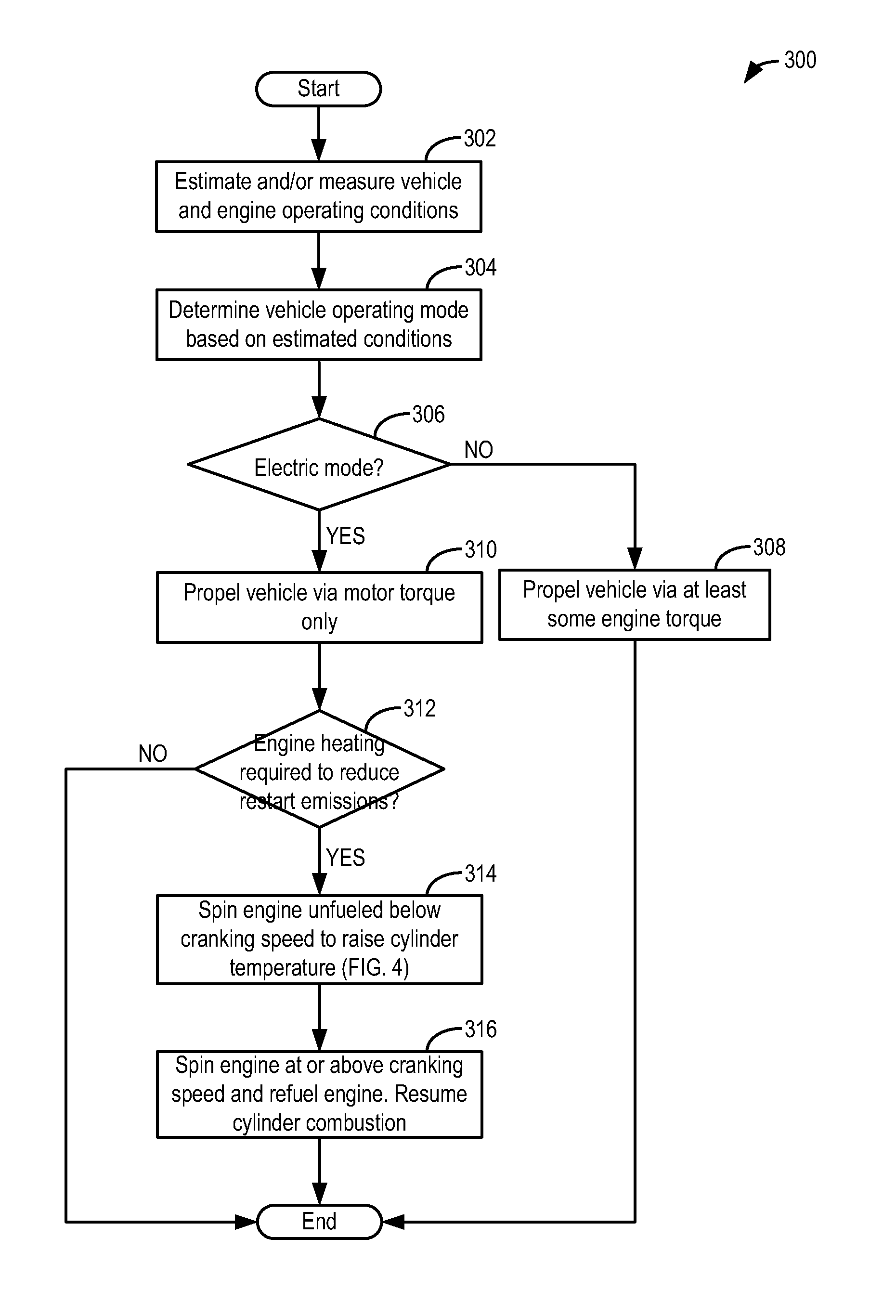
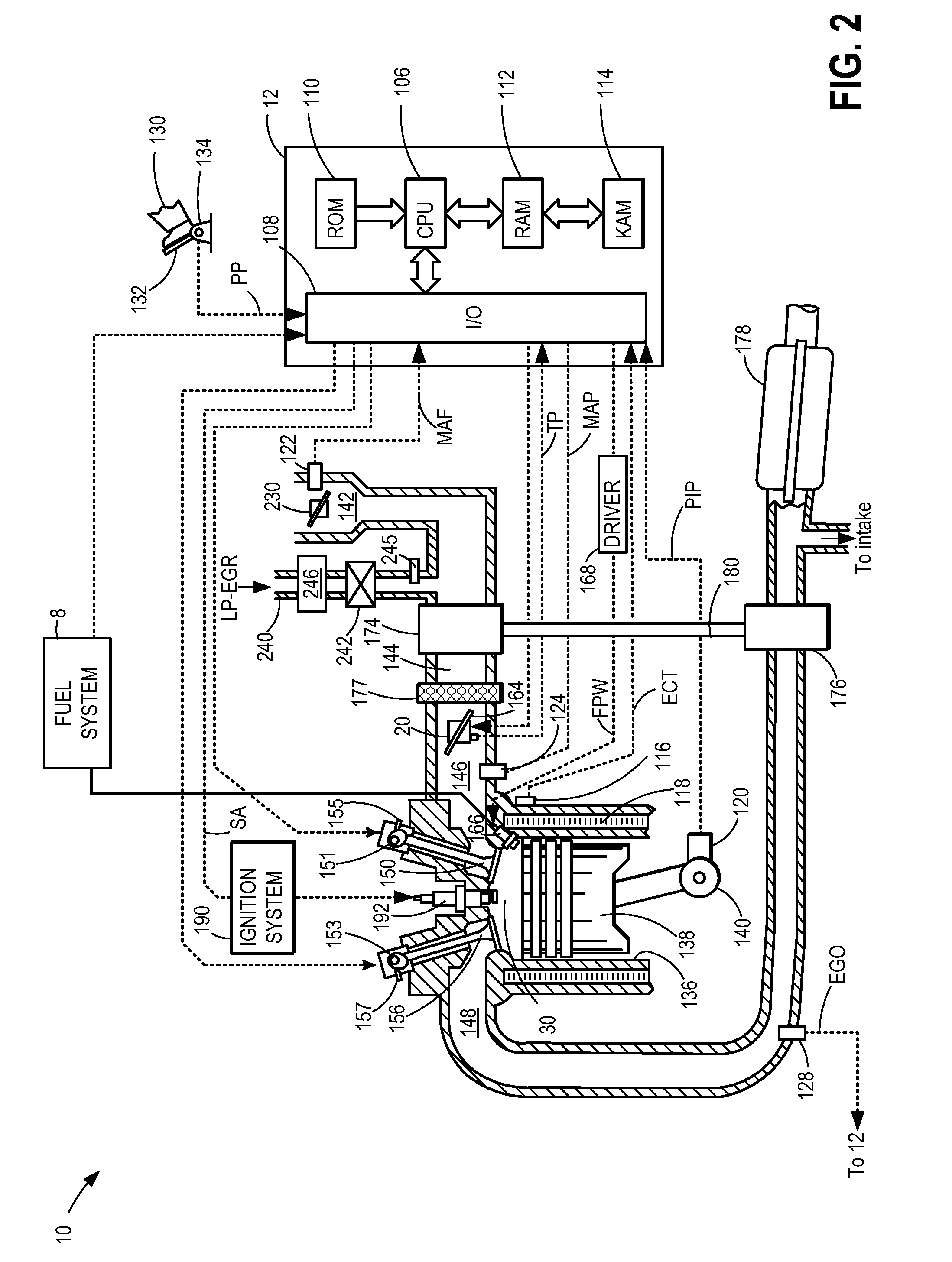
[0015]The following description relates to systems and methods for reducing particulate emissions from an engine, such as the engine system of FIG. 2, coupled in a hybrid vehicle system, such as the plug-in hybrid electric vehicle of FIG. 1. A controller may be configured to perform a routine, such as the example routines of FIGS. 3-4, to rotate the engine, unfueled, during vehicle operation using motor torque, so as to use compression stroke heat transfer (FIG. 6) to heat engine combustion chambers while also raising fuel pressure. The engine may then be further rotated to preposition the engine for the engine restart. An example engine rotation operation is shown at FIG. 5. In this way, the quality of exhaust emissions, particularly during cold-starts, is improved.

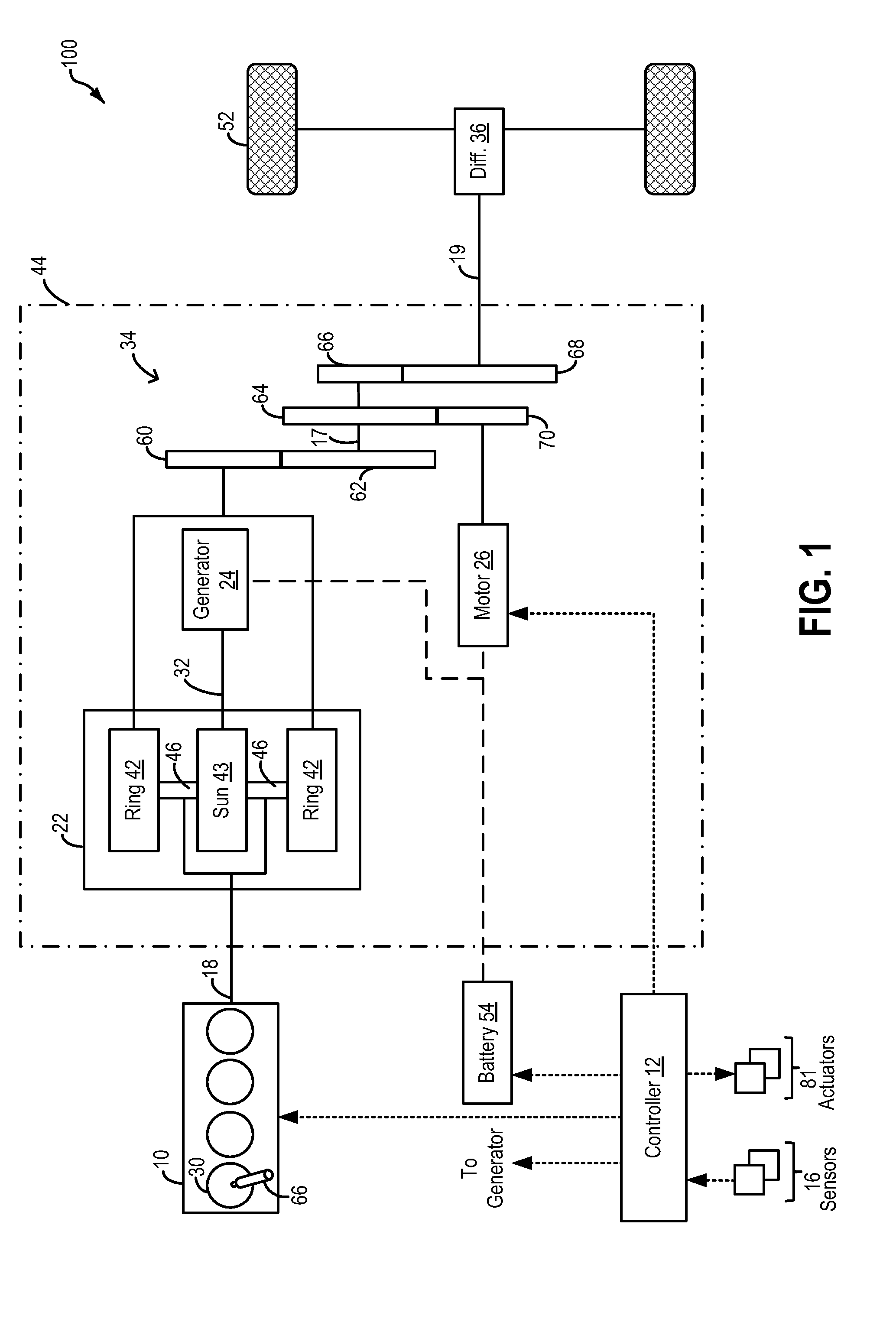
[0016]FIG. 1 depicts a hybrid propulsion system 100 for a vehicle. In the depicted embodiment, the vehicle is a hybrid electric vehicle (HEV). Propulsion system 100 includes an internal combustion engine 10 having a plur...


PUM


Abstract

Methods and systems are provided for slowly rotating an engine, unfueled, via a motor prior to an imminent engine restart to heat the engine. By rotating the engine so that heat generated in the compression stroke of a cylinder can be transferred to cylinder walls, thereby expediting engine warm-up. By warming the engine before a restart, particulate emissions generated during an engine cold-start due to direct injection of fuel can be reduced.

Description

FIELD[0001]The present application relates to methods and systems for controlling engine cranking in a hybrid vehicle system.BACKGROUND AND SUMMARY[0002]Engines may be configured with direct fuel injectors that inject fuel directly into a combustion cylinder (direct injection), and / or with port fuel injectors that inject fuel into a cylinder port (port fuel injection). Direct injection allows higher fuel efficiency and higher power output to be achieved in addition to better enabling the charge cooling effect of the injected fuel.[0003]Direct injected engines, however, can generate more particulate matter (PM) emissions (or soot) due to diffuse flame propagation wherein fuel may not adequately mix with air prior to combustion. Since direct injection, by nature, is a relatively late fuel injection, there may be insufficient time for mixing of the injected fuel with air in the cylinder. In some operating conditions, the liquid droplet may directly impinge on the combustion surfaces su...

Claims


Application Information

Patent Timeline
Patent Type & Authority Patents(United States)
IPC IPC(8): B60W10/06B60W10/08B60W30/192B60W20/00B60W30/18B60W30/194
CPCB60W10/06B60W10/08B60W2710/0688Y10S903/902Y10T477/23B60W30/18018B60W30/192B60W30/194B60W2710/0616B60W2710/0644B60K6/445B60W2510/0676B60W20/40B60W20/16Y02T10/62
Inventor ULREY, JOSEPH NORMANYI, JIANWEN JAMESSHELBY, MICHAEL HOWARDROLLINGER, JOHN ERIC
Owner FORD GLOBAL TECH LLC
Why Eureka
Try Eureka