
Shaft for ablation catheter with balloon

a technology of ablation catheter and shaft, which is applied in the field of shaft for ablation catheter with balloon, can solve the problems of increasing burden on patients, reducing treatment accuracy, and difficult complete deflation, so as to reduce the burden on patients, increase the mixing efficiency of liquid for heating, and shorten the time to uniform surface temperature

Active Publication Date: 2016-05-31
TORAY IND INC
View PDF16 Cites 0 Cited by
  • Summary
  • Abstract
  • Description
  • Claims
  • Application Information

AI Technical Summary

Benefits of technology

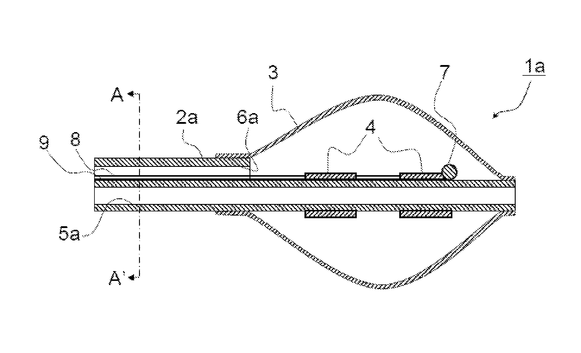
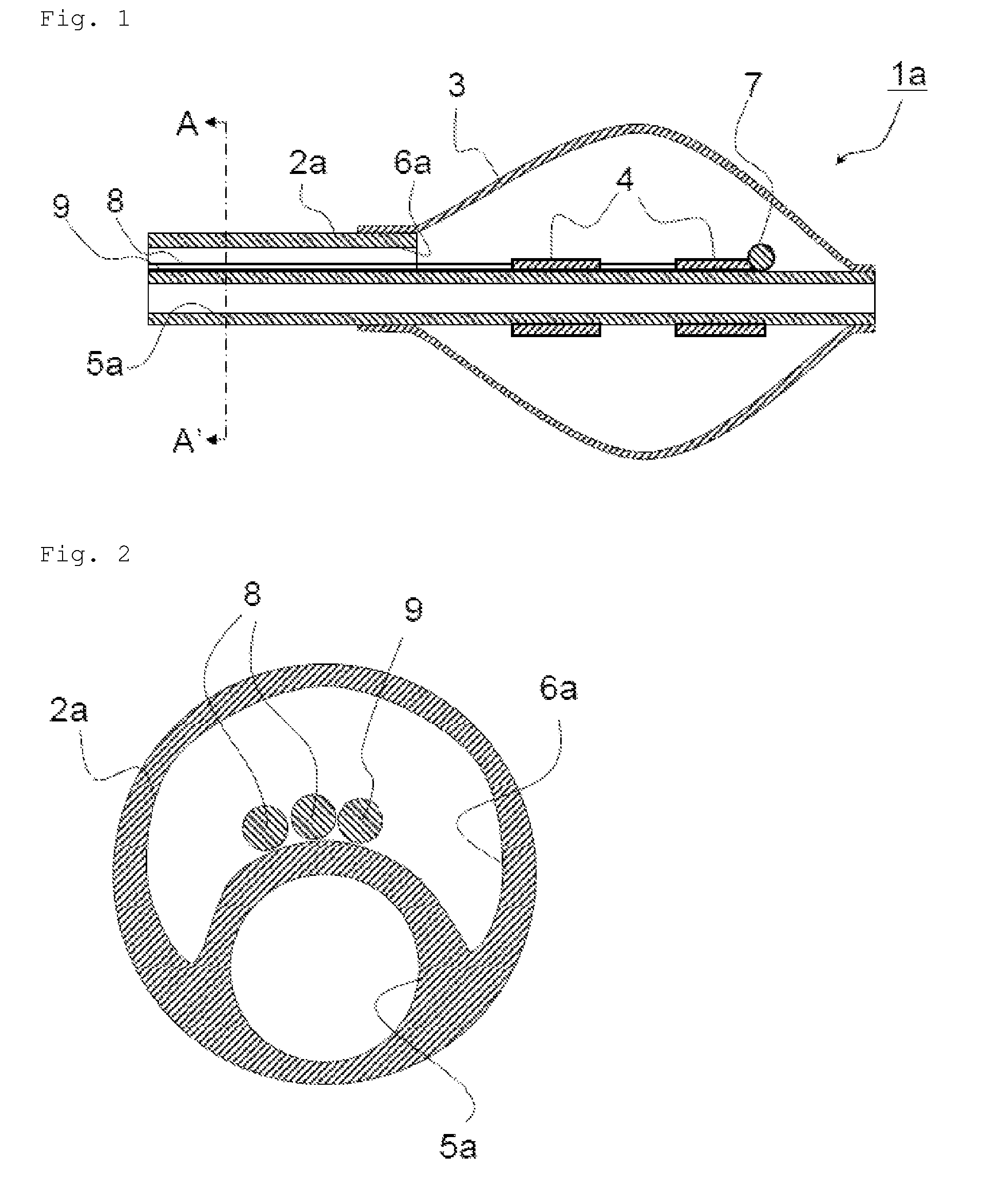
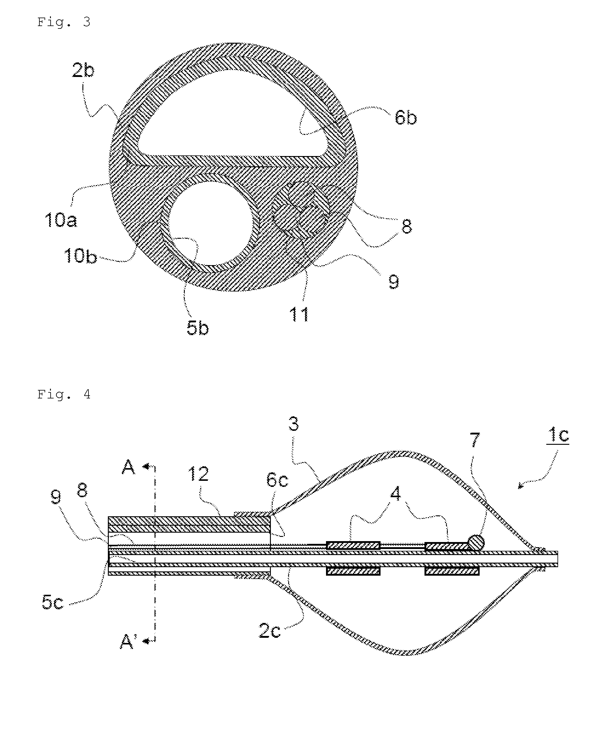
This patent describes a new invention for an ablation catheter with a balloon that can improve the efficiency of liquid heating and prevent air from remaining in the catheter. This leads to faster and safer treatment with reduced discomfort for patients. The invention allows the liquid to flow more smoothly through the catheter, increasing the mixing efficiency with the balloon. This results in a quick and uniform heating of the balloon surface, reducing the duration of the treatment.

Problems solved by technology

In the ablation catheter with a balloon disclosed in Patent Literature 1, since the liquid for heating supplied in the balloon and in the space between the outer cylinder shaft and the inner cylinder shaft is not perfused smoothly, it takes a long time to uniform the surface temperature of the balloon, and a variation occurs in the surface temperature of the balloon, which causes concern about increase in burden on a patient and decrease in treatment accuracy.
Also, since the liquid for heating is not perfused smoothly, air bubbles are attached to the balloon, the inner surface of the outer cylinder shaft, and the outer surface of the inner cylinder shaft even when the liquid is supplied in the balloon and in the space between the outer cylinder shaft and the inner cylinder shaft before treatment to deflate the ablation catheter with a balloon, and complete deflation is difficult.

Method used


Image

  • Shaft for ablation catheter with balloon
  • Shaft for ablation catheter with balloon
  • Shaft for ablation catheter with balloon

Examples


example 1

[0089]A shaft made of polyurethane having a length of 1000 mm and an outer diameter of 3.2 mm and having a guidewire passing lumen 5e with a cross-section perpendicular to a longitudinal direction of the shaft being a circle having a diameter of 1.1 mm, a liquid supplying lumen 6e with a cross-section perpendicular to the longitudinal direction of the shaft being a circle having a diameter of 1.6 mm, and a third lumen 20 with a cross-section perpendicular to the longitudinal direction of the shaft being a circle having a diameter of 1.1 mm was prepared by extrusion molding to obtain a shaft for an ablation catheter with a balloon 2e.

[0090]A part of a range including the liquid supplying lumen 6e and the third lumen 20 of the shaft for an ablation catheter with a balloon 2 from a front end of the shaft for an ablation catheter with a balloon 2e to a position 40 mm distanced in length from the front end was cut off to have the shape of the front portion shown in FIG. 9.

[0091]A copper...

example 2

[0099]A shaft made of polyurethane having a length of 1000 mm and an outer diameter of 3.2 mm and having a guidewire passing lumen 5f with a cross-section perpendicular to a longitudinal direction of the shaft being a circle having a diameter of 1.1 mm and a liquid supplying lumen 6f with a cross-section perpendicular to the longitudinal direction of the shaft being a circle having a diameter of 1.8 mm was prepared by extrusion molding to obtain a shaft for an ablation catheter with a balloon 2f.

[0100]A part of a range including the liquid supplying lumen 6f of the shaft for an ablation catheter with a balloon 2f from a front end of the shaft for an ablation catheter with a balloon 2f to a position 40 mm distanced in length from the front end was cut off to have the shape of the front portion shown in FIG. 11.

[0101]A copper wire plated with silver and undergoing FEP coating having a length of 1300 mm and a diameter of 0.72 mm was used as the lead wire 8, and a constantan wire under...

example 3

[0109]A shaft made of polyurethane having a length of 1000 mm and an outer diameter of 3.6 mm and having a guidewire passing lumen 5g with a cross-section perpendicular to a longitudinal direction of the shaft being a circle having a diameter of 1.2 mm and a liquid supplying lumen 6g with a cross-section perpendicular to the longitudinal direction of the shaft being a semicircle having a diameter of 2.7 mm was prepared by extrusion molding to obtain a shaft for an ablation catheter with a balloon 2g.

[0110]A part of a range including the liquid supplying lumen 6g of the shaft for an ablation catheter with a balloon 2g from a front end of the shaft for an ablation catheter with a balloon 2g to a position 40 mm distanced in length from the front end was cut off to have the shape of the front portion shown in FIG. 13.

[0111]A copper wire plated with silver and undergoing FEP coating having a length of 1300 mm and a diameter of 0.72 mm was used as the lead wire 8, and a constantan wire u...


PUM


Abstract

The stirring efficiency of a heating liquid which is supplied to the balloon of a balloon-equipped ablation catheter is increased to quickly uniformize the surface temperature of the balloon, and air is prevented from remaining in the balloon-equipped ablation catheter to enhance the safety of treatment which uses the balloon-equipped ablation catheter. A shaft for a balloon-equipped ablation catheter, consisting of a single pipe, wherein the shaft has two lumens which communicate from the distal end to the proximal end of the shaft, a first lumen being a guide wire passage lumen which is provided in order to allow a guide wire to pass therethrough, the second lumen being a liquid supply lumen which is provided in order to supply liquid to the inside of the balloon of the balloon-equipped ablation catheter.

Description

CROSS-REFERENCE TO RELATED APPLICATIONS[0001]This application is the U.S. National Phase application of PCT International Application No. PCT / JP2010 / 055632, filed Mar. 30, 2010, and claims priority to Japanese Patent Application No. 2009-085005, filed Mar. 31, 2009, the disclosures of which PCT and priority applications are incorporated herein by reference in their entirely for all purposes.TECHNICAL FIELD[0002]The present invention relates to a shaft for an ablation catheter with a balloon.BACKGROUND OF THE INVENTION[0003]Catheter ablation is a treatment method by inserting an ablation catheter into a cardiac chamber and applying heat between a tip electrode and a counter electrode plate to ablate and remove a myocardial tissue causing an arrhythmia. The catheter ablation is useful mainly for treatment of tachyarrythmias such as a paroxysmal supraventricular tachycardia, an atrial tachycardia, an atrial flutter, and a paroxysmal ventricular tachycardia, and recently, an ablation ca...

Claims


Application Information

Patent Timeline
Patent Type & Authority Patents(United States)
IPC IPC(8): A61B18/04A61B18/14A61B18/00A61F2/958A61M25/10
CPCA61B18/04A61B18/1492A61B2018/1472A61B2018/0022A61B2018/00166A61B2018/00404A61B2018/00577A61B2018/00642A61B2018/00702A61B2018/00791A61B2018/046A61M25/09A61M25/10
Inventor YAGI, TAKAHIROTAKAOKA, MOTOKIMATSUKUMA, AKINORI
Owner TORAY IND INC
Learn More