Generally speaking, it becomes increasingly unlikely that this constraint will be met with each additional sequence fragment to be assembled.
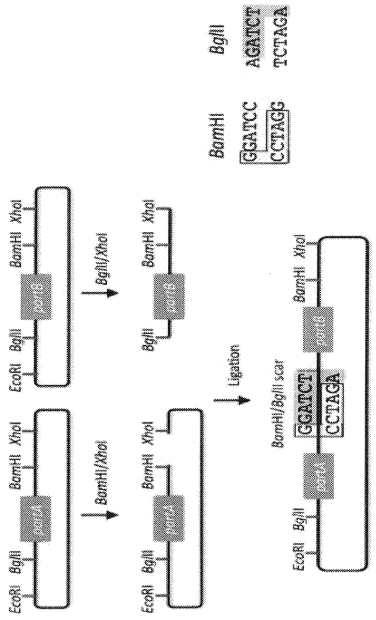
First, there is no control over the existence and sequence of the 6-bp
scars resulting from each binary BioBrick
assembly.
While in many cases, these
scars will not prove problematic, there are scenarios where the scar sequences, affecting coding sequences or mRNA secondary structure, can adversely perturb the desired
protein, RBS, terminator, etc., function.
Third, combinatorial
library diversity generation is potentially at
odds with the BioBrick assembly process, because diversity must be recaptured after each and every binary assembly step (which requires aggregating 5 times as many post-transformation colonies per binary assembly as the sequence diversity to be retained), Fourth, BioBrick assembly only works with previously BioBrick'd parts, and another
cloning method must be used to first create the BioBricks to be assembled.
Gibson is advantageous over SLIC in that it is a simultaneous
one pot reaction (the two-step addition of dCTP is not required), the presence of ligase may boost assembly efficiency, and since the assembly reaction occurs at an elevated temperature relative to SLIC, there may be fewer problems when somewhat stable secondary structures occur at the ends of assembly pieces; the
disadvantage of the Gibson method is that the T5
exonuclease, Phusion
polymerase, and Taq ligase cocktail is more expensive than that required for SLIC (only T4
DNA polymerase, or none at all if mixed or incomplete PCR products are used).
An anecdotal / empirical limitation of the Gibson method is that it works best to assemble DNA fragments that are at least 250 bp in length or longer; this is perhaps due to the likelihood that the 15
exonuclease would entirely chew through a short DNA fragment before it has a chance to anneal and prime the Phusion
polymerase for extension.
The main disadvantages of CPEC is that it is more likely to result in
polymerase-derived mutations than SLIC or Gibson, and mis-priming events are now possible anywhere along the sequences of the fragments to be assembled (as opposed to only at the termini of the fragments), although the Gibson method, depending on how much of a head start the T5
exonuclease has, could suffer from similar drawbacks.
The downside of SLIC / Gibson / CPEC assembly is that we must now design the 5′ flanking homology sequence of each oligo specifically for each assembly junction, a process that can be tedious, laborious, and error-prone.
A major limitation to prior art SLIC / Gibson / CPEC assembly is that the termini of the DNA sequence fragments to be assembled should not have stable single stranded DNA secondary structure, such as a hairpin or a
stem loop (as might be anticipated to occur within a terminator sequence), as this would directly compete with the required single-stranded annealing / priming of neighboring assembly fragments.
Repeated sequences (such as the repeated terminators and promoters in the example above are often obstacles to SLIC / Gibson / CPEC assembly, since assembly is directed by
sequence homology, and if two distinct assembly fragments are identical at one terminus (such as the 3′ termini of the terminators in the example above), this can lead to assemblies that do not contain all of the desired parts, or may contain parts arranged in the wrong order.
Finally, SLIC / Gibson / CPEC might not be the optimal choice for combinatorial assembly if sequence diversity occurs at the very ends of the sequence fragments to be assembled (within about 15 bps of the termini), since this will preclude the reuse of the same homology sequences throughout all of the combinations.
These limitations, which assert that the SLIC / Gibson / CPEC assembly methods are not completely sequence-independent, are largely addressed by the Golden-gate assembly method.
The limitation of using uncut plasmids as the
source material is that the destination vector, and all of the parts to be assembled, must already be cloned into a Golden-gate format
plasmid system, and the overhang sequences are set in stone.
The downside of Golden-gate assembly (as for SLIC / Gibson / CPEC) is that we must now design the 4-bp overhang sequences for each assembly junction and incorporate them into the 5′ flanking sequence of each oligo, a process that can be tedious, laborious, and error-prone.
Perhaps the most significant limitation of the Golden-gate method is that it is less sequence-independent than SLIC / Gibson / CPEC, in the sense that, like BioBrick assembly, the selected type IIs recognition site (e.g. BsaI) should be absent from the internal portions of all of the DNA fragments to be assembled.
In addition, since the overhangs are only 4 bp in length, and we would like at least 1 and preferably 2 bp to be different between each and every overhang in an assembly reaction, it may not be possible to find a set of overhangs that are compatible with each other that allows for a single multi-part assembly step, especially if the number of fragments to assemble together becomes large (greater than about 10 fragments), or if the %
GC content of the fragment termini is highly skewed to one extreme or the other.

