

Process for producing mevalonic acid
- Summary
- Abstract
- Description
- Claims
- Application Information
AI Technical Summary
Benefits of technology
Problems solved by technology
Method used
Image

Examples
example 1
Search for Genes on Database
[0129] Using acetyl-coenzyme A acetyltransferase, 3-hydroxy-3-methylglutaryl-coenzyme A synthase and 3-hydroxy-3-methylglutaryl coenzyme A reductase as a query, key word search was carried out on the nucleotide sequence database GenBank.
[0130] As a consequence, sequence information was obtained as to the following enzyme genes derived from the bacteria, i.e., acetyl-CoA acetyltransferase / HMG-CoA reductase gene. mvaE (GenBank Accession No.: AF290092) and HMG-CoA-synthase gene mvaS (GenBank Accession No.: AF290092) of Enterococcus faecalis, acetyl-CoA acetyltransferase / HMG-CoA reductase gene mvaE (GenBank. Accession No.: AF290094) and HMG-CoA synthase gene mvaS (GenBank -Accession. No.: AF290094) of Enterococcus faecium, HMG-CoA reductase gene mvaA (GenBank Accession No.: AF290098) and HMG-CoA synthase gene mvaS (GenBank Accession No.: AF290098) of Streptococcus pneumoniae, HMG-CoA reductase gene mvaA (GenBank Accession No.: AF290096) and HMG-CoA synthase...
example 2
Preparation of E. coli Strain that Expresses Mevalonic Acid Biosynthetic Enzyme Genes Derived from Enterococcus faecalis
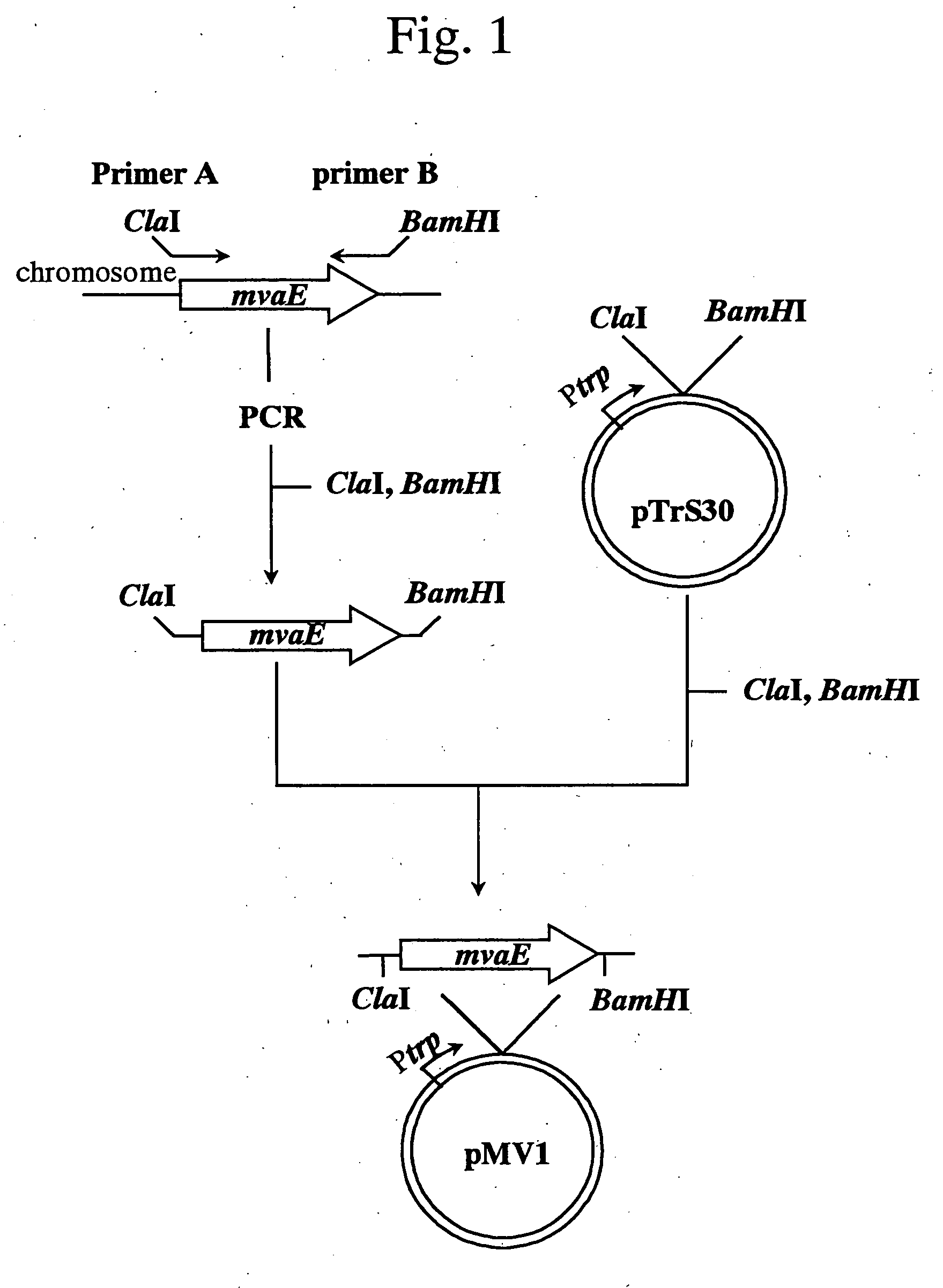
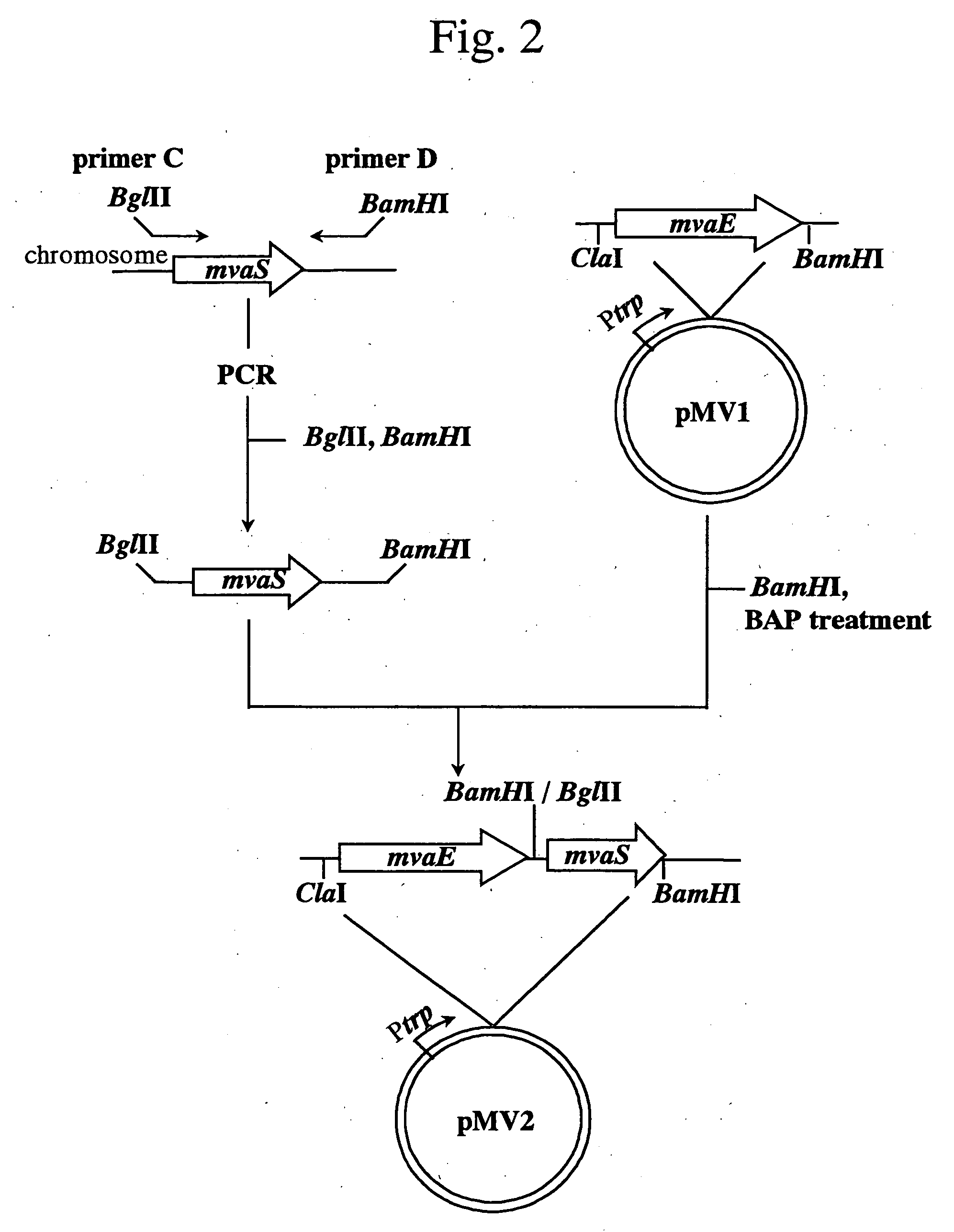
[0131] (1) Isolation of mvaE and mvas Derived from Enterococcus faecalis
[0132] Among the sequence information obtained in Example 1, a sequence (GenBank Accession No.: AF290092) containing the gene mvaE encoding acetyl-CoA acetyltransferase / HMG-CoA reductase and the gene mvaS encoding HMG-CoA synthase of Enterococcus faecalis (hereinafter, abbreviated as E. faecalis) was utilized to obtain the gene fragments as described below. A nucleotide sequence of mvaE of E. faecalis (hereinafter, merely described as mvaE) is shown in SEQ ID NO: 1; an amino acid sequence of acetyl-CoA acetyltransferase / HMG-CoA reductase encoded by the gene is shown in SEQ ID NO: 2; a nucleotide sequence of mvas of E. faecalis (hereinafter, merely described as mvaS) is shown in SEQ ID NO: 3; and an amino acid sequence of HMG-CoA synthase encoded by the gene is shown in SEQ ID NO: 4.
[0133] Fi...
example 3
Production of Mevalonic Acid by E. coli Strain XL1-Blue / pMV2
[0148] (1) Production of Mevalonic Acid by Culturing in a Test Tube
[0149] The E. coli strain XL1-Blue / pMV2 obtained in Example 2 was inoculated into 8 mL of an LB medium (10 g / L triptone, 5 g / L yeast extract, 10 g / L sodium chloride, pH 7.0) containing 50 μg / mL ampicillin in a large test tube, and cultured at 28° C. for 17 hrs. The culture medium was inoculated into 8 mL of an M9X medium [16 g / L dipotassium hydrogenphosphate, 14 g / L potassium dihydrogenphosphate, 5 g / L ammonium sulfate, 1 g / L citric acid (anhydride), 5 g / L peptone (manufactured by Kyokuto Pharmaceutical Industrial Co., Ltd.), 20 g / L glucose, 0.8 mg / L vitamin B1, 25 mg / L magnesium sulfate heptahydrate, 50 mg / L ferrous sulfate heptahydrate, pH 7.2, adjusted with 10 mol / L sodium hydroxide: Glucose, vitamin B1, magnesium sulfate heptahydrate and ferrous sulfate heptahydrate were separately added after autoclaving] containing 100 μg / mL ampicillin in a large tes...
PUM
 Abstract
Description
Claims
Application Information