Reinforced battery electrodes

a battery electrode and reinforced technology, applied in the field of electrode materials and structures for lithiumion batteries, can solve the problems of less restraining electrode materials on the next and subsequent cycles, affecting the performance of electrodes, so as to reduce active surface area, increase electrode capacity, and increase surface area

Active Publication Date: 2016-06-07
GM GLOBAL TECH OPERATIONS LLC
View PDF4 Cites 57 Cited by
  • Summary
  • Abstract
  • Description
  • Claims
  • Application Information

AI Technical Summary

Benefits of technology

[0010]The reinforcements may deform in concert with the electrode material to maintain mechanical and electrical continuity across the reinforcement-electrode material interface while limiting the strains experienced by the electrode material during lithiation and de-lithiation. By limiting such strains, fracture of the electrode material is rendered less likely. But even if electrode material fractures do occur, the ability of the elongated reinforcement to bridge any fracture may minimize loss of the fractured, broken-off electrode material pieces. The reinforcement may also maintain electrical continuity across a fracture so that even broken-off portions of an electrode may continue to contribute battery capacity.
[0017]Tin may be electrodeposited on copper, with its applied SMA reinforcements. Tin may also be applied by electroless plating or by a displacement deposition reaction promoted by complexing with a CN− ion. The current collector may also be dipped in molten tin (melting point about 232° C.) or small beads or pellets of tin, may be applied to the collector, suitably fluxed, and melted in situ in a vacuum or inert atmosphere. Since tin will wet a clean copper surface a generally uniform coating may be achieved.
[0018]The high capacity negative electrode material may be applied to any desired depth but not greater than the thickness of the reinforcement stack or the length of any individual reinforcement, so that the entire thickness of the electrode material has reinforcements embedded within it. Applying an electrode material thickness less than the thickness of the reinforcement stack may enable a more porous or creviced surface on the electrode to permit electrolyte access to a larger surface area. A thicker deposit, comparable to the depth of the reinforcement layer may reduce the active surface area but increase the capacity of the electrode for lithium absorption.
[0019]In another embodiment a paste of commingled high capacity electrode material particles and SMA reinforcements with a binder and suitable solvent may be applied to the surface of the current collector to a suitable thickness. After evaporation of the solvent, the resulting aggregate, may offer greater access to electrolyte while still retaining resistance to spalling and fracture of the high capacity electrode material because of the action of the embedded reinforcements in keying the particles together for mutual support.
[0021]The pattern may be chosen to form elongated or compact reinforcements or a combination of both. This approach may be employed to produce wire- or rod-like geometries but also enables incorporating features in the reinforcements which enable more extensive engagement of the reinforcement with the electrode material.

Problems solved by technology

As stated, such electrode materials typically experience significant volume change as lithium is absorbed or released.
Such a set may prevent it from relaxing to its original unstrained dimension and so render it less capable of restraining electrode material on the next and subsequent cycles.

Method used


Image

  • Reinforced battery electrodes
  • Reinforced battery electrodes
  • Reinforced battery electrodes

Examples


Embodiment Construction

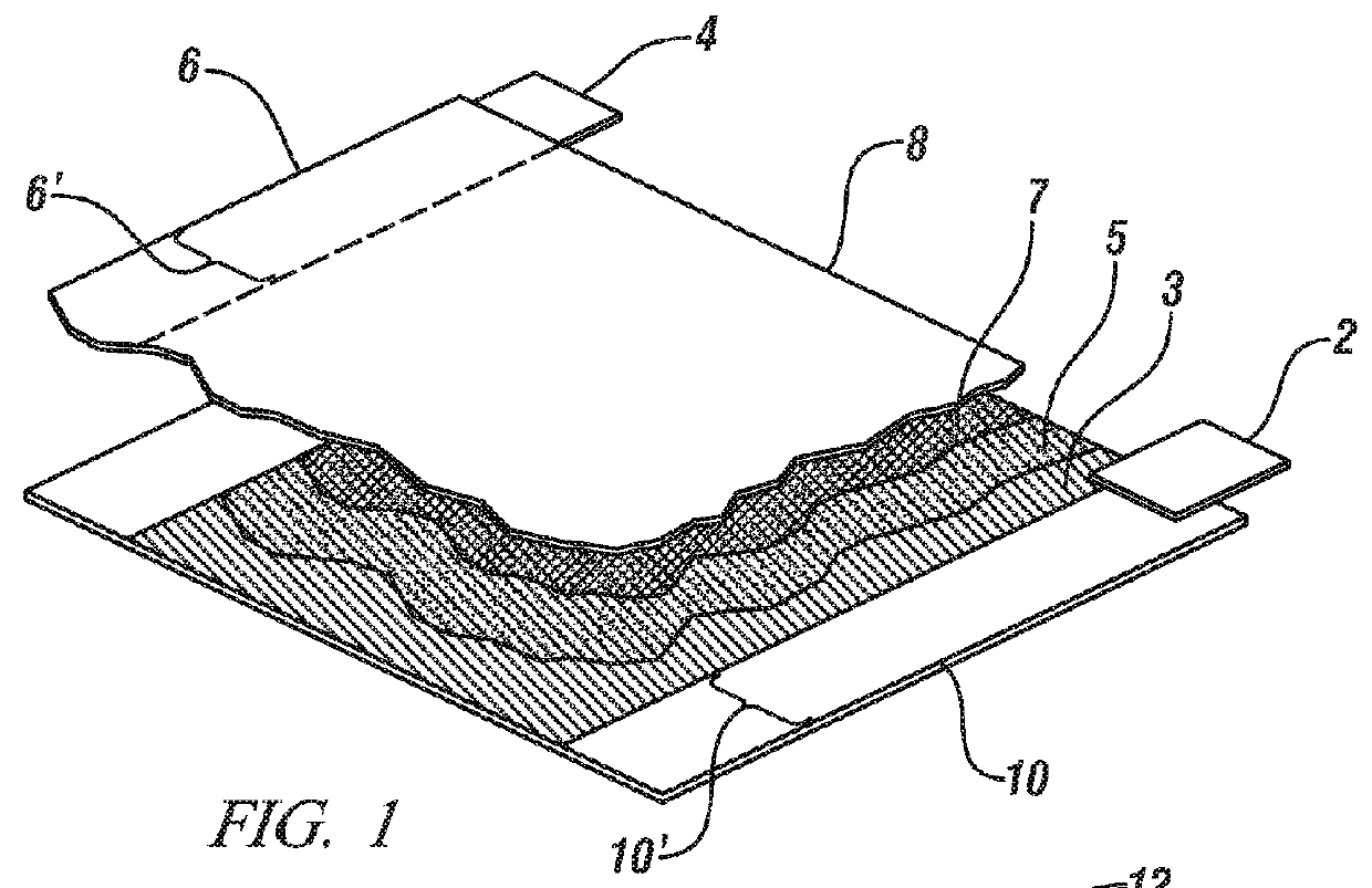
[0028]Lithium ion batteries generally comprise a plurality of interconnected individual cells arranged so as to satisfy the voltage and electrical energy storage, or capacity requirements, of a particular application. An exemplary structure for such an individual cell is shown in cutaway perspective FIG. 1 and comprises facing negative 3 and positive 7 electrodes separated by an electrically non-conductive spacer 5. Each of the electrodes is coated on or attached to, an electrically conductive current collector commonly fabricated of copper (for the negative electrode 10) and aluminum (for the positive electrode 6). Conductive tabs 2, 4 may be attached to uncoated regions of the cell such as strips 10′, 6′ for tapping the electrical current generated by the cell. The configuration illustrated, which is exemplary and not limiting, is suitable for a cylindrical battery, for example an AA battery, in which the electrodes are rolled into a cylindrical shape and cell connections are made...


PUM

PropertyMeasurementUnit
thicknessaaaaaaaaaa
thicknessaaaaaaaaaa
thicknessaaaaaaaaaa

Abstract

The gravimetric and volumetric efficiency of lithium ion batteries may be increased if high capacity materials like tin and silicon may be employed as the lithium-accepting host in the negative electrode of the battery. But both tin and silicon, when fully charged with lithium, undergo expansions of up to 300% and generate appreciable internal stresses which have potential to spall off material from the electrode on each discharge-charge cycle, resulting in a progressive reduction in battery capacity, also known as battery fade. A method of reinforcing such electrode materials by incorporating within them fiber reinforcements or shaped, elongated reinforcements fabricated of shape memory alloy is described. Electrode materials incorporating such reinforcements are less prone to damage under applied stress and so less prone to battery fade.

Description

TECHNICAL FIELD[0001]This invention pertains to electrode materials and structures for the cells of lithium-ion batteries in which lithium ions are repeatedly inserted into and removed from electrode active material during charging and discharging of the battery. More specifically, this invention pertains to methods and treatments for incorporating in such electrode materials reinforcing features of shape memory alloy to reduce electrode strain and promote enhanced battery life.BACKGROUND OF THE INVENTION[0002]Secondary or rechargeable lithium-ion batteries may be used as electric energy storage systems for powering electric and hybrid electric vehicles. These batteries comprise a plurality of suitably interconnected electrochemical cells each of which undergoes a specific chemical reaction capable of generating electrical energy. When suitably arranged, these cells provide a predetermined electrical current at a specified electrical potential to an external load, such as an electri...

Claims


Application Information

Patent Timeline
Patent Type & Authority Patents(United States)
IPC IPC(8): H01M4/36H01M4/134H01M4/62B22F7/00C22C9/00C22C19/03H01M4/66H01M4/38C22C28/00H01M4/1395H01M10/052H01M4/02
CPCH01M4/134B22F7/004C22C9/00C22C19/03C22C28/00H01M4/626H01M4/667B22F2999/00H01M4/1395H01M4/661H01M10/052H01M2004/021Y02E60/122Y02P70/54Y02T10/7011B22F3/002Y02E60/10Y02T10/70Y02P70/50
Inventor SACHDEV, ANIL K.VERBRUGGE, MARK W.XIAO, XINGCHENGSAROSI, PETER MAXWELL
Owner GM GLOBAL TECH OPERATIONS LLC
Why Eureka
Try Eureka