Adaptive rail power amplifier technology

a power amplifier and adapter rail technology, applied in the direction of low frequency amplifiers, transducer casings/cabinets/supports, electrical transducers, etc., can solve the problems of reducing the size of both transformers tb, capacitors c+ and c, and design suffer from high emi/rfi emissions, so as to achieve the same level of performance and reduce parts and complexity

Active Publication Date: 2016-07-26
WALLER JR JAMES K
View PDF8 Cites 4 Cited by
  • Summary
  • Abstract
  • Description
  • Claims
  • Application Information

AI Technical Summary

Benefits of technology

[0011]The adaptive rail high current charge pump circuit includes a charge storage device, also called a flying capacitor, with one of its plates connected to two high current switches. One high current switch is connected to the supply through a ferrite bead. The other high current switch is connected to ground through another ferrite bead. The other plate of the flying capacitor is connected to two high current diodes. The first high current diode is connected to the battery. The other high current diode is connected to the output node and to second charge storage capacitor to smooth the output voltage and deliver output current to the load. A dead zone circuit generates the proper timing to control the high current switches. The dead zone outputs are connected to the gate control of the high current switches. The charge pump circuit is controlled by the output of a comparator which compares the output signal of the power amplifier with the rail voltage, producing a dynamically varying pulsed output signal in response to the output swing of the amplifier and the adaptive rail output of the charge pump circuit.
[0013]In accordance with an added feature of the invention, multiple sections or blocks of the charge pump circuitry are combined to provide even higher output voltages, thereby increasing further the output voltage swing of the amplifier and allowing the use of higher efficiency higher impedance speaker loads.

Problems solved by technology

The typical switching frequency of this type of switch mode power supply is between 25 KHz and 100 KHz, which reduces the size of both the transformer T1 and the output filter capacitors C+ and C. Due to the high switching frequency and the large current pulses generated when switching a high current square wave at high frequencies, this design suffers from high EMI / RFI emissions.
When the audio power amplifier 14 is delivering large amounts of current to the speaker load, the RFI emissions can actually reduce FM radio reception and, in some cases, cause complete loss of certain AM radio band frequencies.
The main tradeoff of this embodiment is that the MOSFETs that drive the positive adaptive rail and negative adaptive rail will see a slight increase in dissipated heat due to using them in a linear mode of operation.

Method used


Image

  • Adaptive rail power amplifier technology
  • Adaptive rail power amplifier technology
  • Adaptive rail power amplifier technology

Examples


Embodiment Construction

[0036]In the following description of the Figures, similar reference symbols designate corresponding structural parts or functional blocks.

The Prior Art Automotive Aftermarket Power Amplifier

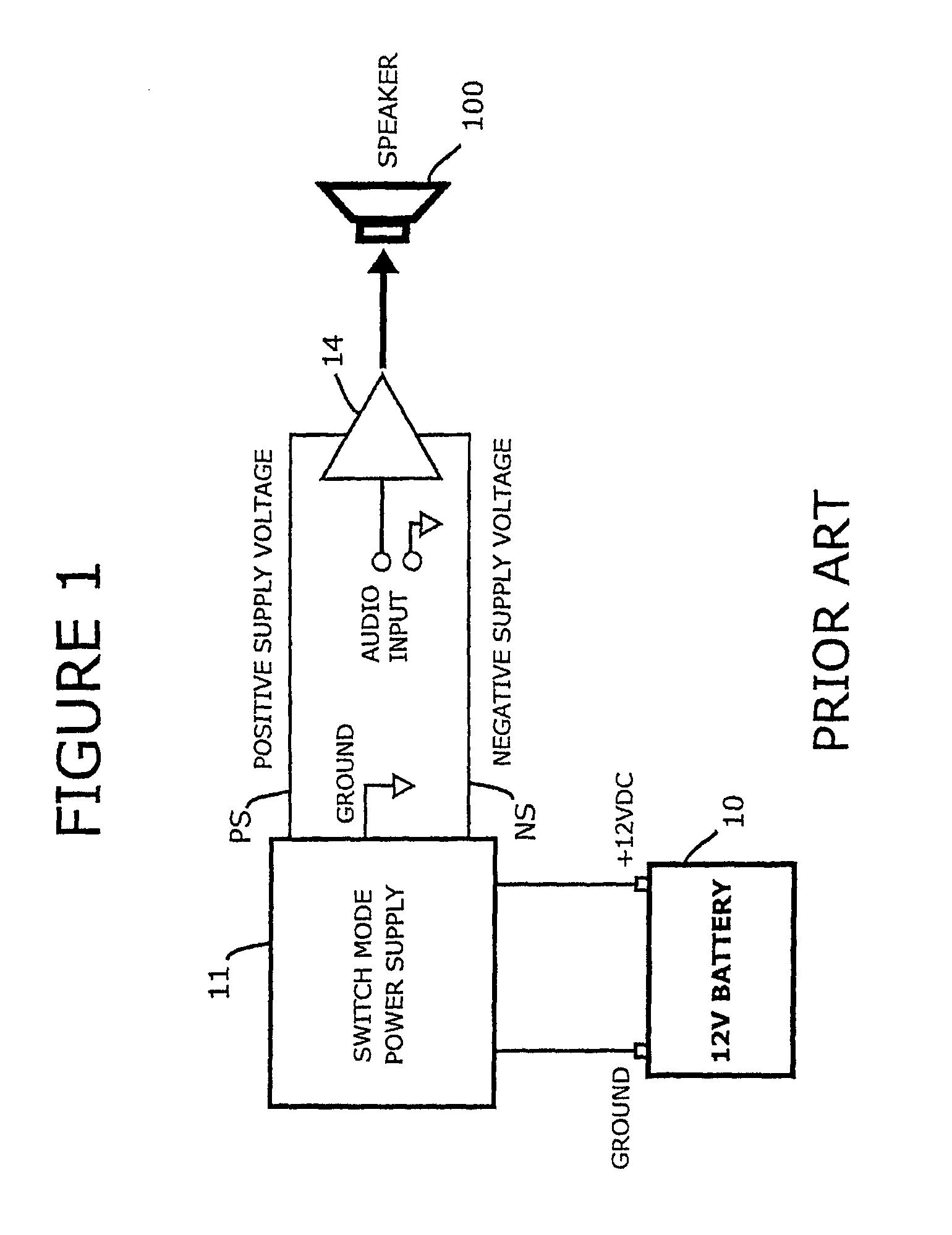
[0037]Turning first to FIG. 1, a block diagram of the typical aftermarket automotive power amplifier is shown. The switch mode power supply 11 and the audio power amplifier 14 are contained in one chassis or unit. A 12 volt battery 10 provides the input power to the switch mode power supply 11 via a +12 volt and ground connection. The switch mode power supply 11 converts the 12 volt battery voltage to a bipolar output voltage referenced to ground, providing a positive output voltage PS and a negative output voltage NS, which supplies bipolar power to the amplifier 14. The audio amplifier 14 receives an audio input signal and amplifies this audio input signal to drive a speaker 100.

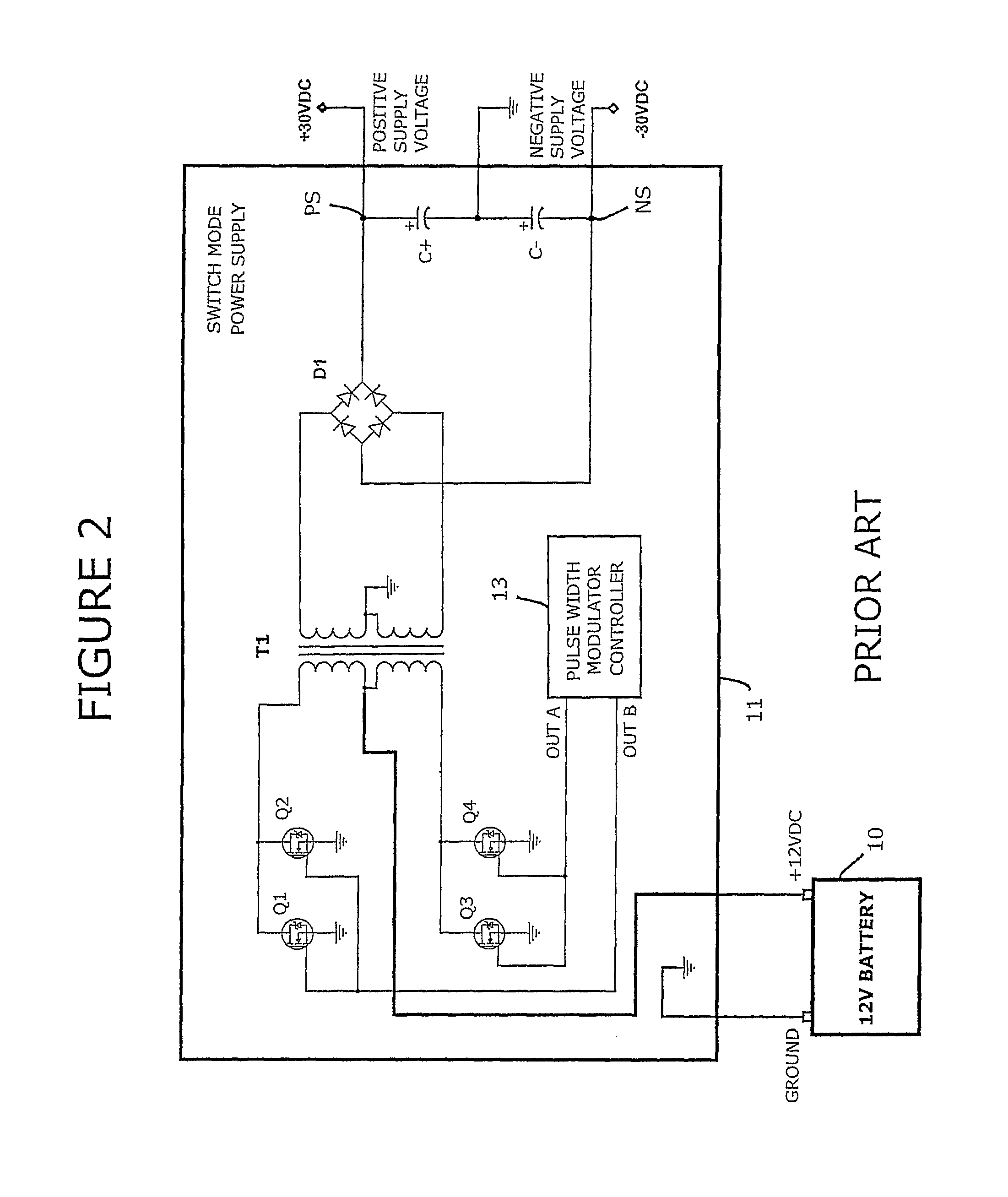
[0038]Looking at FIG. 2, a simplified schematic of the switch mode power supply 11 of FIG. 1 is shown. The switch mo...


PUM


Abstract

Adaptive rail power amplifier technology processes an audio signal by feeding the audio signal to the power amplifier to produce an output signal, applying positive and negative power supply voltages centered with respect to the audio signal to the positive and negative power supply rails of the power amplifier, comparing the output signal with the positive and negative power supply rail voltages to produce dynamically varying positive and negative control signals, feeding the positive and negative control signals to positive and negative high current charge pumps and adding supplemental positive and negative voltages from the positive and negative charge pumps to the positive and negative power supply rails to produce a linear adaptive rail voltage which tracks the output signal.

Description

CROSS-REFERENCE TO PENDING APPLICATIONS[0001]This application claims priority to U.S. Provisional Patent Application No. 61 / 622,696, filed on Apr. 11, 2012.BACKGROUND OF THE INVENTION[0002]Numerous designs have been developed and used over the past years incorporating various methods of providing a modulated power supply for an audio amplifier in order to improve efficiency and reduce dissipation of the power devices. Many prior art designs have disclosed either dual or multiple rails that switch to a higher voltage when the output swing of the amplifier is near clipping. These designs have been termed Class H and Class G where a secondary or multiple rail voltages are selected as required based on amplifier output swing. More complex designs have been realized with continuously variable rails that track the input signal and adjust the power supply rails so as to maintain a constant voltage between the output devices output swing and the power supply rail voltage. Most of these ampl...

Claims


Application Information

Patent Timeline
Patent Type & Authority Patents(United States)
IPC IPC(8): H03F1/02H04R3/00
CPCH04R3/00H03F1/0233H03F1/0238H03F3/183H03F3/217H03F2200/375
Inventor WALLER, JR., JAMES K.
Owner WALLER JR JAMES K
Why Eureka
Try Eureka