Manufacturing method of an eyeless suture needle

a manufacturing method and needle technology, applied in the field of eyeless suture needle manufacturing method, can solve the problems of difficult laser welding pipe to a very thin needle body portion, not being practicable, and difficult to obtain such drawing strength, so as to prevent the generation of burrs, reduce the sharp edge of the chamfered portion, and restrain the thread from being torn

Active Publication Date: 2016-08-09
IKEN KOUGYO +1
View PDF21 Cites 2 Cited by
  • Summary
  • Abstract
  • Description
  • Claims
  • Application Information

AI Technical Summary

Benefits of technology

[0020]According to the manufacturing method of the eyeless suture needle of the present invention, by joining the pipe-like member with uniform concavity and convexity formed on an inner circumferential surface in advance, it is able to easily provide a thread attaching portion having a blind hole. Furthermore, it is able to lessen the shape error of the blind hole, to make the surface roughness of the inner surface of the blind hole uniform, and to make the depth of the blind hole sufficient. Therefore, it is able to increase and equalize the drawing strength of the suture thread which is caulked and fixed to the blind hole.
[0030]In such case, the sharpness of the edge of the chamfered portion is reduced compared to a case of providing chamfer process to the opening portion of the pipe-like member by a single chamfer tool, and also it is able to prevent the generation of burr, and restrain the suture thread from being torn off by the edge.

Problems solved by technology

However, it is very difficult to laser weld the pipe to a very thin needle body portion, and therefore it has not been practically used.
However, it is difficult to obtain such drawing strength.
On the other hand, if the caulking pressure is strengthened, problems occur such as the breakage of the suture needle or the like.
Even by carefully adjusting the caulking pressure, it is very difficult to completely dissolve the defect of the drawing strength.
Furthermore, a needle separated from the suture thread by a drawing strength test cannot be reused, and this becomes a cause of high cost.

Method used


Image

  • Manufacturing method of an eyeless suture needle
  • Manufacturing method of an eyeless suture needle
  • Manufacturing method of an eyeless suture needle

Examples


Embodiment Construction

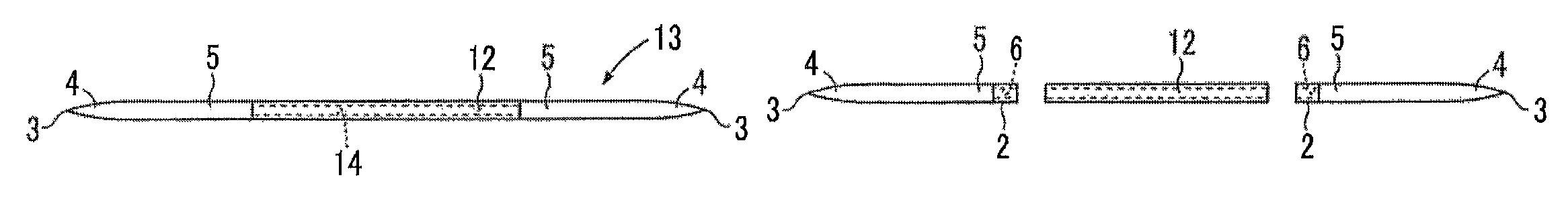
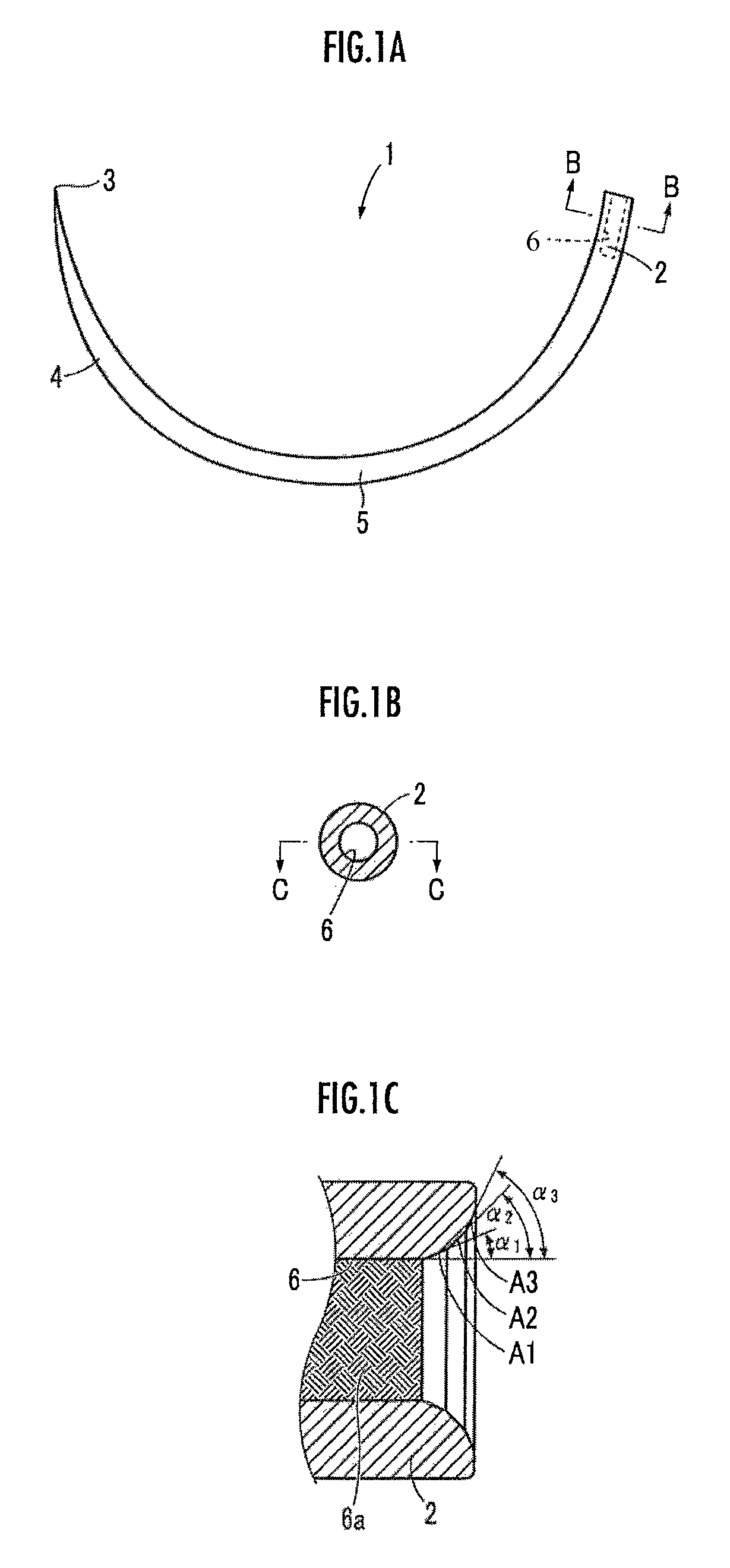
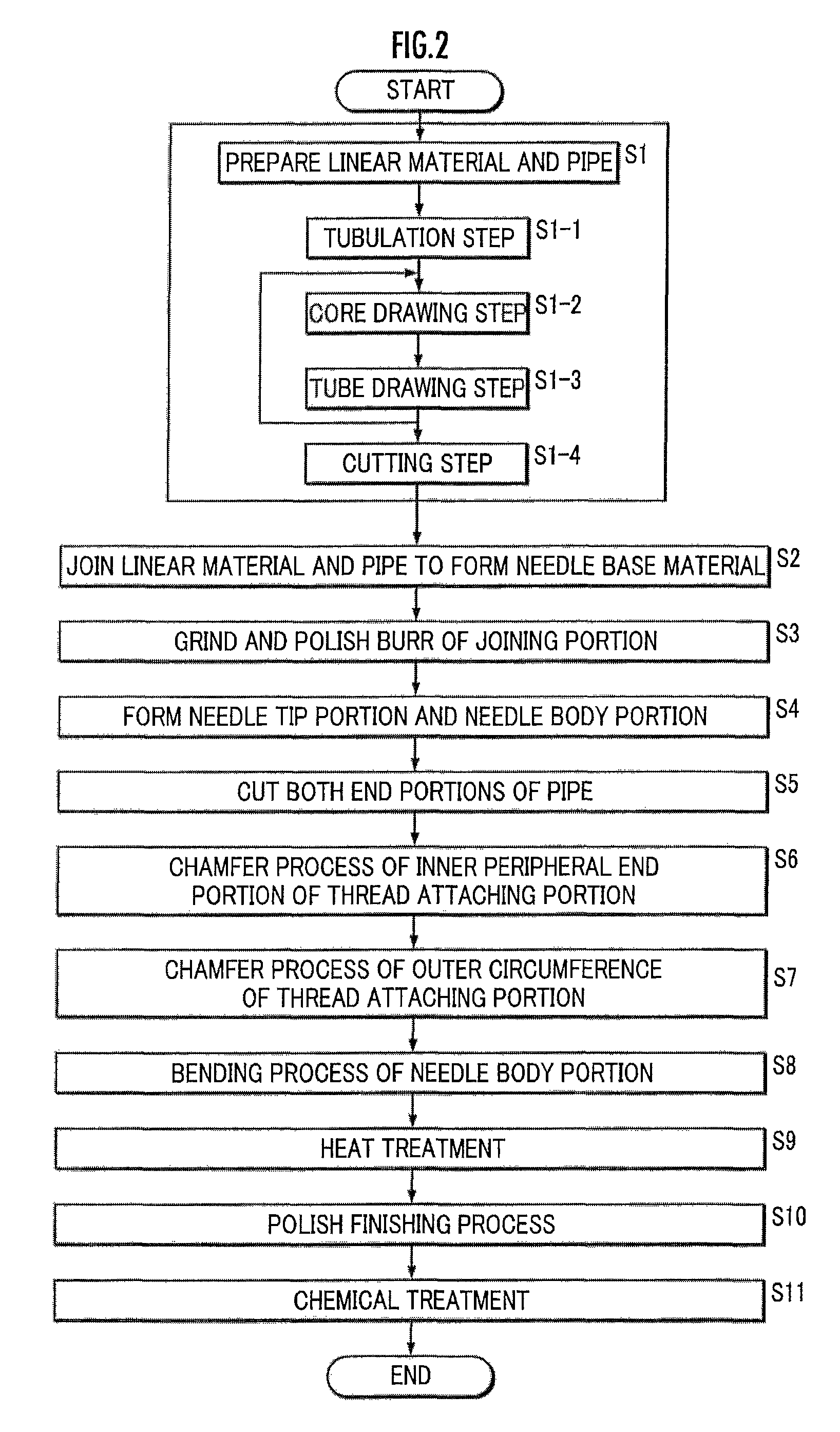
[0036]Hereinafter, an eyeless suture needle and a manufacturing method thereof are explained with reference to the drawings. First, the cause of insufficient drawing strength of a suture thread caulked and fixed to a blind hole of a thread attaching portion of the eyeless suture needle will be considered.

[0037][Cause of Insufficient Drawing Strength]

[0038]The direct cause of insufficient drawing strength of the suture thread is considered to be the defect of separation of the suture thread by dropping out from the blind hole or separation of the suture thread by being torn off. As a result of analysis by the inventor, it was found that these defects are related to hole diameter error of the blind hole, outer diameter error of the suture thread, surface roughness of an inner surface of the blind hole, shape of an opening portion of the blind hole, and a depth of the blind hole. Therefore, if each of these factors are made to be appropriate, it is able to largely decrease the possibil...


PUM

PropertyMeasurementUnit
surface roughness Rzaaaaaaaaaa
diameteraaaaaaaaaa
lengthaaaaaaaaaa

Abstract

A pipe element tube 23 is manufactured by a manufacturing method including step S1-1 for obtaining the pipe element tube 23 by rolling a stainless steel plate material 21 and welding an abutting portion, a core drawing step S1-2 for reducing a diameter and adjusting a thickness of the pipe element tube 23 by using a cored bar 24, and a tube drawing step S1-3 for reducing the diameter and adjusting an outer form of the pipe element tube 23 without using a cored bar. By adjusting repetition times of the core drawing step S1-2 and the tube drawing step S1-3, a uniform concavity and convexity are provided on an inner circumferential surface of the pipe element tube 23. Then a pipe 12 having an annular shaped cross section obtained by cutting the pipe element tube 23 and a linear material 11 having a circular cross section are joined (S2).

Description

TECHNICAL FIELD[0001]The present invention relates to a manufacturing method of an eyeless suture needle.[0002]In a surgical operation and the like, an eyeless suture needle in which a suture thread is caulked and fixed to a blind hole of a thread attaching portion is used. Conventionally, first a needle tip portion and a needle body portion are processed to a round rod material, and then an opposite side of the needle tip portion is cut to a predetermined length. Thereafter, the blind hole of the thread attaching portion is formed by opening a hole to the cut surface to be parallel to a needle axis by a drill, laser, or electric discharge machining or the like (refer to Patent Literatures 1 to 3). Moreover, in a case of manufacturing a relatively long eyeless suture needle, there were cases where the needle tip portion and the needle body portion was processed by cutting to a predetermined length after providing the blind hole.[0003]There has been also proposed to process the needl...

Claims


Application Information

Patent Timeline
Patent Type & Authority Patents(United States)
IPC IPC(8): A61B17/06B21G1/08B24B19/16B21J5/02B21G5/02A61B17/00
CPCB21G1/08A61B17/06066B21J5/027B24B19/16A61B2017/00526A61B2017/06028
Inventor NAKAYAMA, YOKICHINAKAYAMA, SHINICHIRO
Owner IKEN KOUGYO
Why Eureka
Try Eureka