
Lighting tiles

a technology of light-emitting tiles and light-emitting plates, which is applied in the field of light-emitting plates, can solve the problems of reducing the aperture ratio, and achieve the effects of reducing the height of electrically conductive plates, reducing the aperture ratio, and increasing the aperture ratio

Inactive Publication Date: 2016-11-08
CAMBRIDGE DISPLAY TECH LTD
View PDF19 Cites 2 Cited by
  • Summary
  • Abstract
  • Description
  • Claims
  • Application Information

AI Technical Summary

Benefits of technology

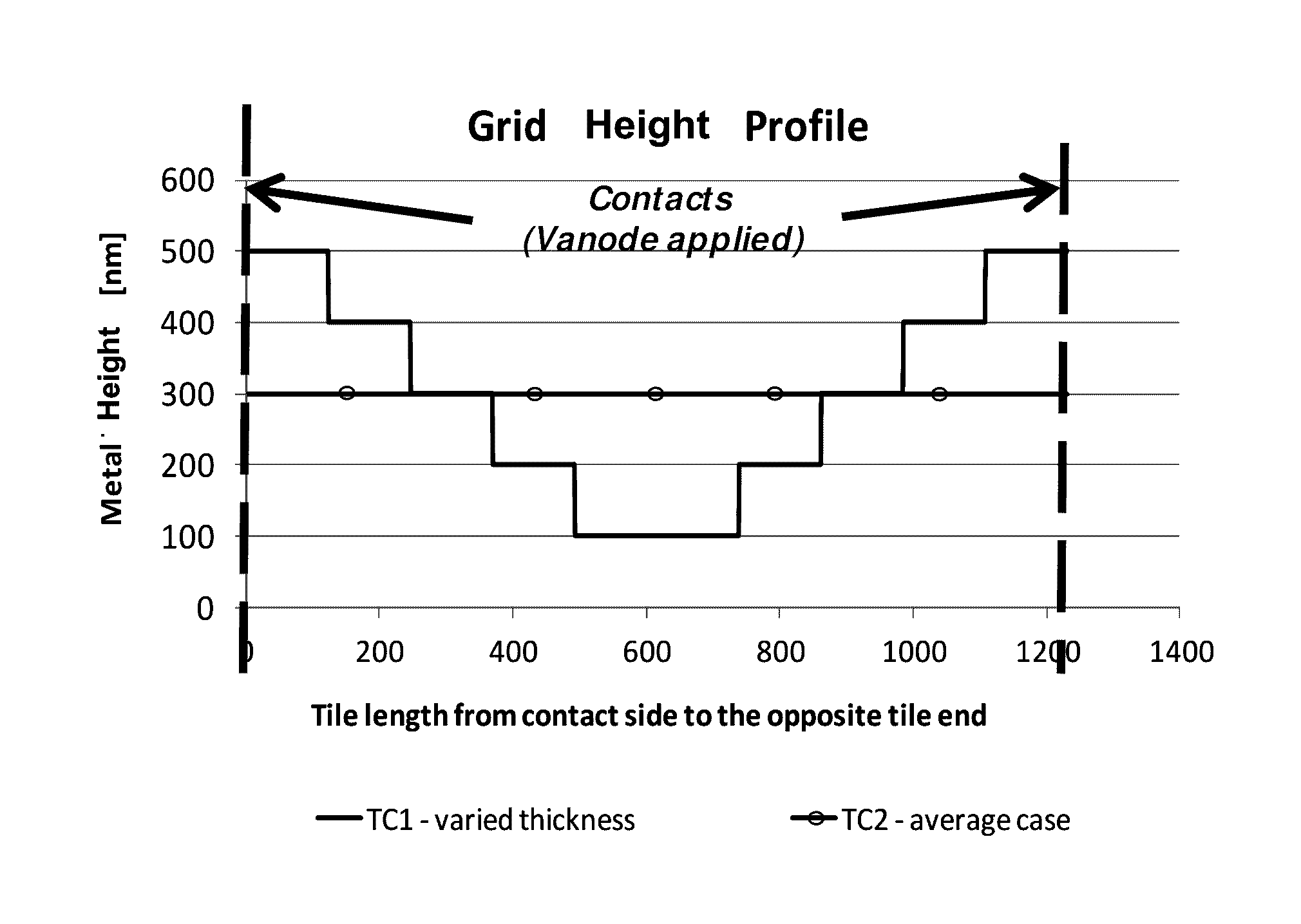
This approach results in a more uniform luminance profile and increased aperture ratio, with luminance maintained to better than 95% across the tile, enhancing the efficiency and performance of large-area OLED devices.

Problems solved by technology

However this also generally results in a decrease in aperture ratio.

Method used


Image

  • Lighting tiles
  • Lighting tiles
  • Lighting tiles

Examples


Embodiment Construction

[0033]Embodiments of the invention that we will describe may be used with any type of lighting tile, including organic light emitting diode (OLED)-based devices and the related, but simpler, light-emitting electrochemical cell (LEC)-based devices. Embodiments of the invention may be used with both so-called bottom-emitting and top-emitting devices. It is helpful for understanding the invention to briefly outline some features of OLED devices.

Organic Light Emitting Diodes

[0034]Organic light emitting diodes (OLEDs) may be coloured (red, green and blue) or white. In this specification references to organic LEDs include organometallic LEDs, and OLEDs fabricated using either polymers or small molecules. Examples of polymer-based OLEDs are described in WO 90 / 13148, WO 95 / 06400 and WO 99 / 48160; examples of so-called small molecule based devices are described in U.S. Pat. No. 4,539,507.

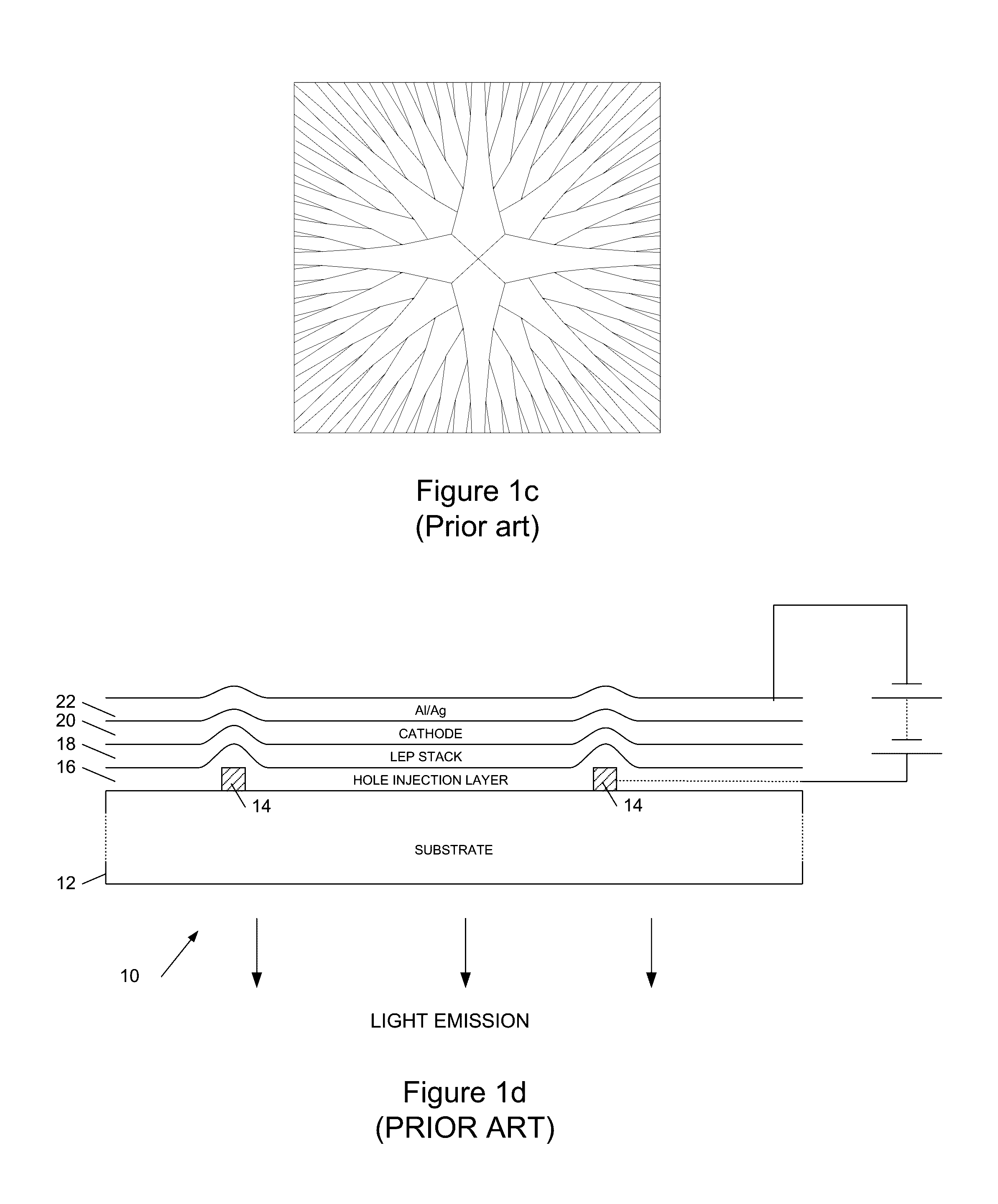
[0035]Referring to FIG. 1d, this shows a vertical cross-section through a portion of an OLED lighting tile...


PUM

PropertyMeasurementUnit
dimensionaaaaaaaaaa
heightaaaaaaaaaa
widthaaaaaaaaaa

Abstract

We describe a lighting tile having a substrate bearing an electrode structure, the electrode structure comprising: a plurality of electrically conductive tracks disposed over said substrate; and an electrical connection region connecting to said plurality of tracks; wherein the height of said tracks tapers away from said connection region to compensate for a reduction in luminance from said lighting tile array from the electrical connection region which arises from a non-uniform voltage drop which appears along the tracks in use. Advantageously the tracks are fabricated by electroplating: then, as the rate of deposition is determined by the voltage drop along a track during plating, the height of the deposited tracks, and therefore their resistance, will match the profile required in operation to compensate for the reduction in luminance which would otherwise occur.

Description

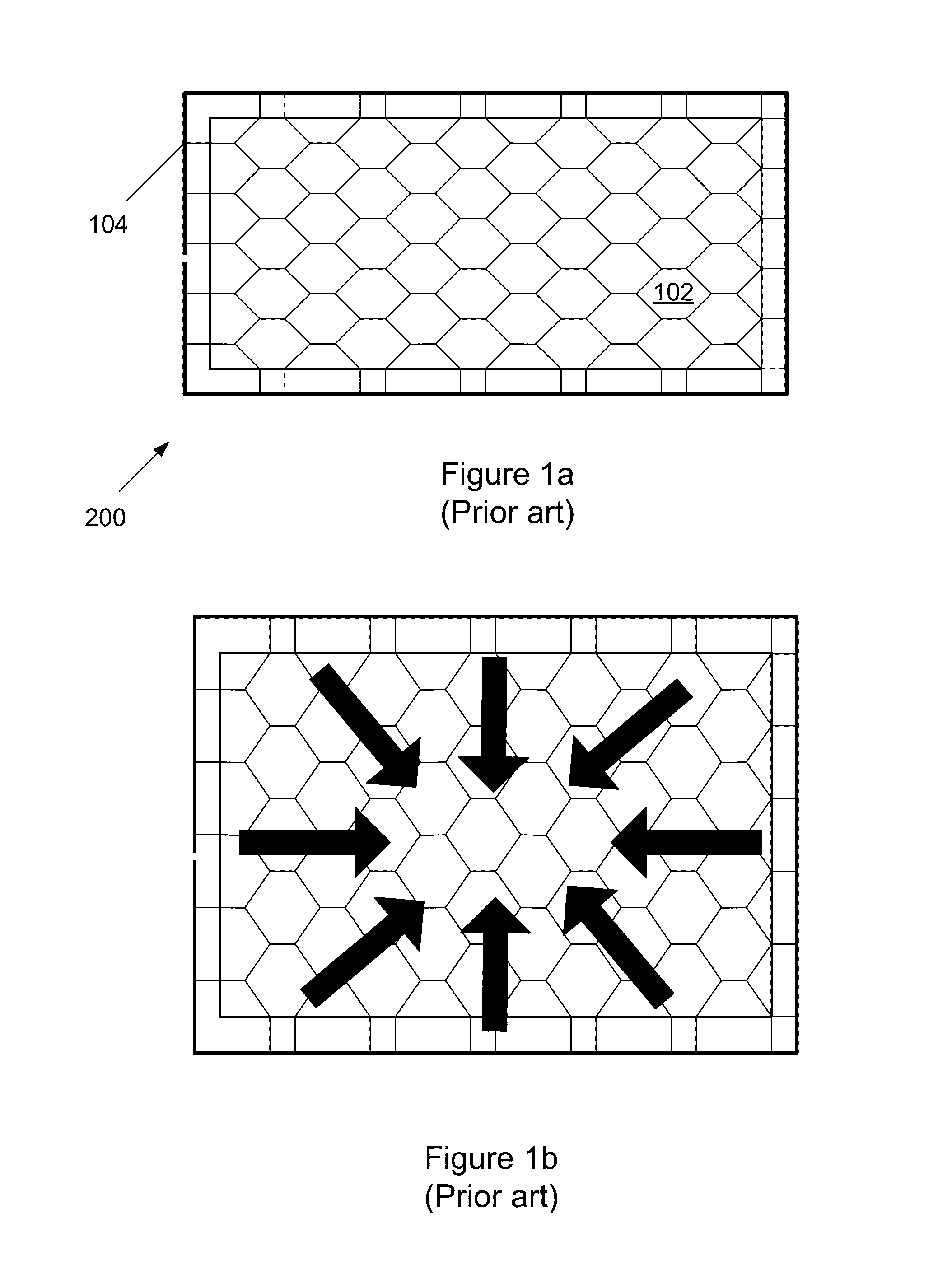
FIELD OF THE INVENTION[0001]This invention relates to lighting tiles and to organic electronic devices, and to methods for fabricating such tiles and devices.BACKGROUND TO THE INVENTION[0002]As described in our patent application GB2482110, a common approach to boost the conductivity of the anode connection of a large-area organic light-emitting diode (OLED) lighting tile is to use a matrix of electrically conductive tracks. As shown in FIG. 1a, a lighting tile 200 generally has (anode) electrode tracks defining a hexagonal or square grid 102, with an electrical busbar 104 surrounding the grid (the opening shown is to facilitate connection with the counter electrode).[0003]FIG. 1b illustrates that within a given area of the tile, the current primarily flows through the anode electrode in a single dominant direction. For example, if the current is supplied from all edges of the tile, the predominant direction of the current is towards the laterally central position of the lighting ti...

Claims


Application Information

Patent Timeline
Patent Type & Authority Patents(United States)
IPC IPC(8): H01L29/08C25D5/54C25D5/34C25D5/02H01L51/56H01L51/52H01L51/00C25D7/12H10K99/00
CPCC25D7/126C25D5/02C25D5/34C25D5/54H01L51/0021H01L51/5203H01L51/5212H01L51/56H01L2251/56H01L2251/5361H10K59/80516H10K71/00H10K71/60H10K50/805H10K50/814
Inventor BAKER, COLINRANKOV, ALEKSANDRA
Owner CAMBRIDGE DISPLAY TECH LTD
Learn More