
Moving-coil type stereo pickup cartridge

a pickup cartridge and moving coil technology, applied in piezoelectric/electrostrictive gramophone pickups, electrical transducers, electrical apparatus, etc., can solve the problems of low signal generation efficiency, low sound quality, and inability to achieve high production efficiency, simple shape, and uniform quality

Active Publication Date: 2016-11-15
AUDIO-TECHNICA
View PDF10 Cites 1 Cited by
  • Summary
  • Abstract
  • Description
  • Claims
  • Application Information

AI Technical Summary

Benefits of technology

The invention is a moving-coil type stereo pickup cartridge that aims to improve productivity and channel separation with a simple and perfect circular shape generating coil. The cartridge includes a vibration unit with a cantilever and stylus, and a magnetic circuit with a gap and a V-shaped notch. The coil is designed to have a high output with low impedance and effectively reduce crosstalk between channels. The cartridge is easy to manufacture and has a uniform quality.

Problems solved by technology

On the other hand, the air-core type MC cartridge, which is the latter, has a technical problem that the generation efficiency of the signal is low, but a reproduced signal thereof is hardly influenced by magnetostriction (hysteresis distortion) caused by a ferromagnetic body to be employed in the iron-core type described above.
However, there is a technical problem that deflection of the cantilever or distortion by moment is caused to impair a sound quality due to the power generation using the cantilever.
Further, the generating coil is disposed in a root portion of the cantilever, and thus, an amplitude operation of the generating coil is smaller than amplitude of a sound track engraved on a record, and accordingly, the generation efficiency is extremely low.
According to such a configuration, an impedance of the generating coil serving as a signal source is large while an effective mass as the generating coil is small, and as a result thereof, it is difficult to prepare the requirements described above as the MC cartridge.
According to such a configuration, it is difficult to produce a delicate mechanism of the pantograph-like armature and the generating coil of the so-called Japanese rice ball type, and thus, it is difficult to obtain the MC cartridge having a high productivity and a uniform quality.

Method used


Image

  • Moving-coil type stereo pickup cartridge
  • Moving-coil type stereo pickup cartridge
  • Moving-coil type stereo pickup cartridge

Examples


Embodiment Construction

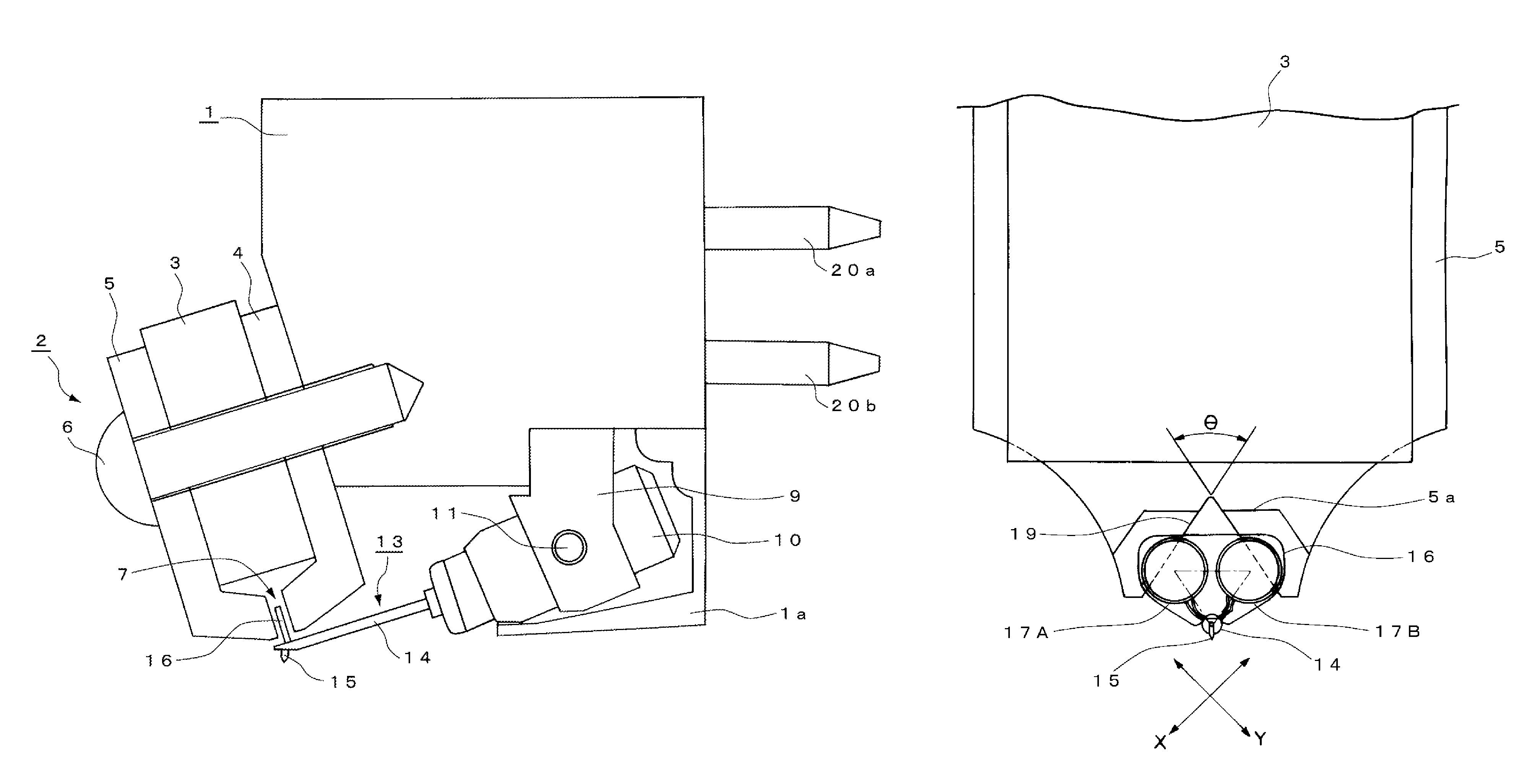
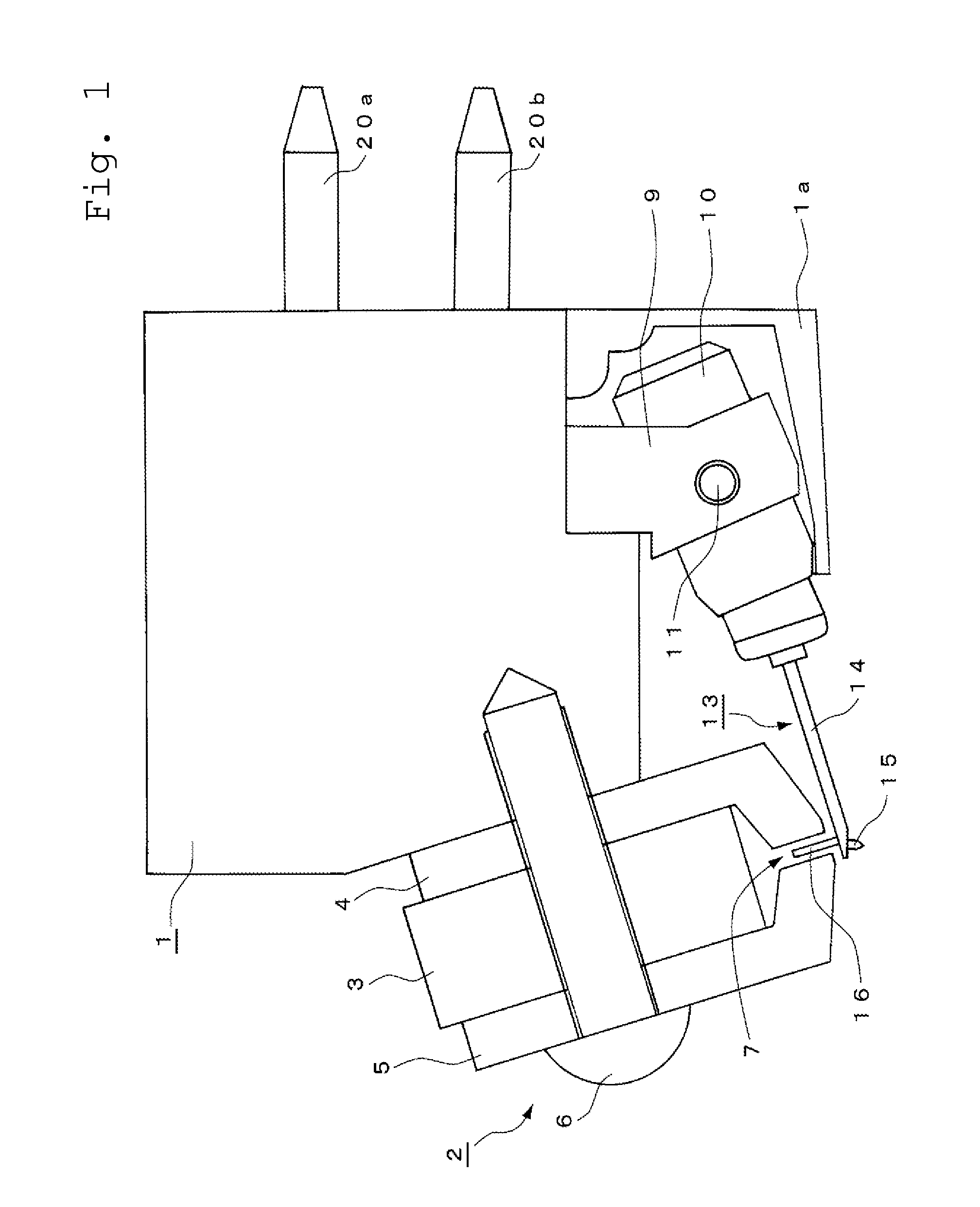
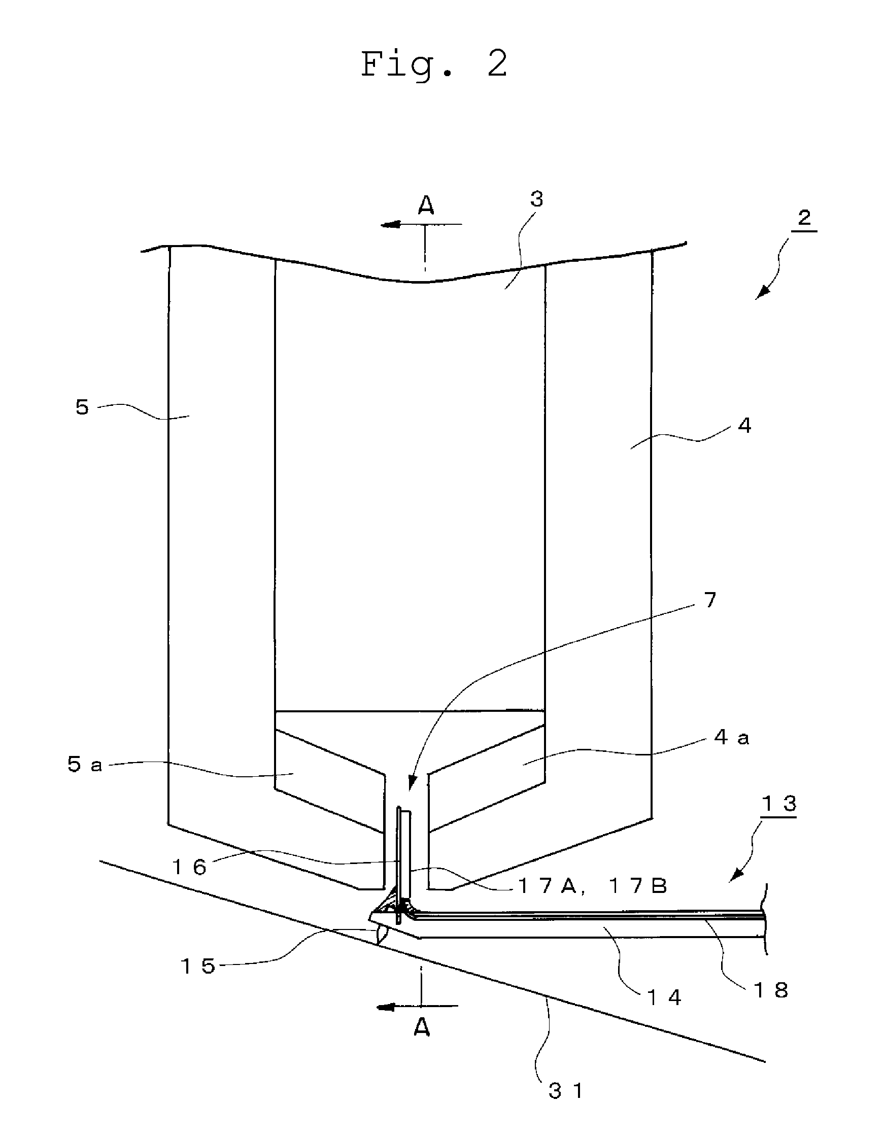
[0033]A description will be given regarding an MC cartridge according to the invention on the basis of embodiments illustrated in the drawings. Incidentally, it should be noted that, in each drawing to be described hereinafter, the same parts are illustrated using the same reference numerals, but reference numerals are assigned to typical parts in some drawings because of space limitations, and the detailed configurations may be described by quoting reference numerals used in other drawings.

[0034]As illustrated in the overall configuration of FIG. 1, the MC cartridge is configured of a vibration unit and a magnetic circuit and a casing that supports the vibration unit and the magnetic circuit when elements thereof are roughly divided.

[0035]That is, a prismatic magnet 3 forming a magnetic circuit 2 and a pair of yokes 4 and 5, which are disposed to sandwich the magnet 3 while opposing a magnetic pole of the magnet 3 are attached to a front end portion of a casing 1 using a bolt 6 tha...


PUM


Abstract

Provided are a vibration unit which includes a pair of right and left coils that vibrate in response to vibration of a stylus attached to a cantilever and a magnetic circuit which includes a magnet and a pair of yokes and forms a magnetic path. The coils to be disposed in a gap between the pair of yokes are flat coils having perfect circular shapes, and V-shaped notches are formed on opposing surfaces, with the coils interposed therebetween, of the pair of yokes 4. An intersection angle of the V-shaped notch is set to be an angle to allow channel separation between right and left output signals to be obtained by the pair of coils to be equal to or larger than 20 db.

Description

RELATED APPLICATIONS[0001]The present application is based on, and claims priority from, Japanese Application No. JP2014-262384 filed Dec. 25, 2014, the disclosure of which is hereby incorporated by reference herein in its entirety.BACKGROUND OF THE INVENTION[0002]Field of the Invention[0003]This invention relates to a moving-coil type pickup cartridge that extracts a signal from a 45-45 stereo record, and particularly to a moving-coil type stereo pickup cartridge capable of obtaining a high productivity and a uniform quality by utilizing a generating coil with a simple shape and, and further, reducing crosstalk between right and left output signals.[0004]Description of the Related Art[0005]An iron-core type and an air-core type, roughly divided, have been proposed as moving-coil type stereo pickup cartridges (hereinafter, also referred to simply as MC cartridges).[0006]The iron-core type MC cartridge, which is the former, has a representative one that is called Ortofon type in whic...

Claims


Application Information

Patent Timeline
Patent Type & Authority Patents(United States)
IPC IPC(8): H04R9/12H04R11/08H04R9/16H04R11/12H04R19/10H04R17/08H04R9/02
CPCH04R9/12H04R9/16H04R11/08H04R9/025H04R11/12H04R17/08H04R19/10
Inventor MIYATA, MITSUO
Owner AUDIO-TECHNICA
Learn More