Radio frequency power source having precise power detector
a technology of rf power supply and detector, which is applied in the direction of resistance/reactance/impedence, instruments, transmission monitoring, etc., can solve the problems of inability to achieve a thin line width, inability of process equipment to process wafers with a smaller line width, and inability to achieve the consistency of rf power detection accuracy. achieve high precision, wide detection range, and good consistency of accuracy
- Summary
- Abstract
- Description
- Claims
- Application Information
AI Technical Summary
Benefits of technology
Problems solved by technology
Method used
Image
Examples
first embodiment
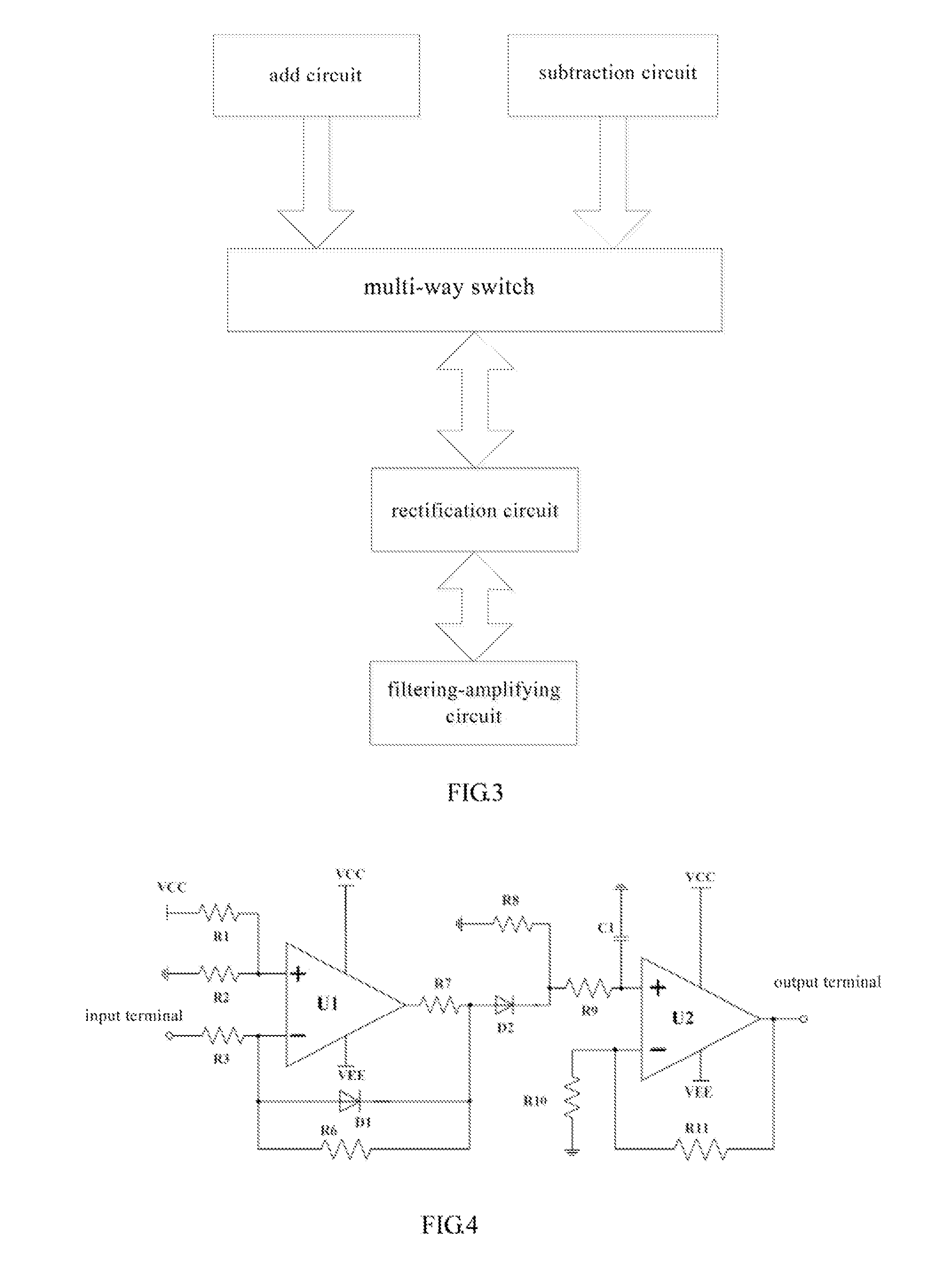
[0031]It is shown in FIG. 4 that a rectification circuit and a filtering-amplifying circuit of the precise detecting module of the present invention. The rectification circuit mainly comprises a rectifying operational amplifier U1 and detecting diodes D1, D2. An anode of the detecting diode D1 is connected to an inverting input terminal of the rectifying operational amplifier U1, and a cathode of the detecting diode D1 is connected to an output terminal of the rectifying operational amplifier U1. The detecting diode D2 is disposed between the output terminal of the rectifying operational amplifier U1 and an input terminal of the filtering-amplifying circuit.
[0032]The detecting diodes D1, D2 may be Schottky diodes with low break-over voltage, preferably IN5711 model diodes. The rectifying operational amplifier is a high-speed operational amplifier with a bandwidth greater than 1 GHz, preferably a high-speed operational amplifier OPA657 with 1.6 GHz bandwidth made of Texas Instruments...
second embodiment
[0036]It is shown in FIG. 5 that the rectification circuit and the filtering-amplifying circuit of the precise detecting module of the present invention. By comparing with the embodiment shown in FIG. 4, the embodiment shown in FIG. 5 only has modifications with respect to the input resistors of the rectification circuit. Instead of using one input resistor R3, the embodiment shown in FIG. 5 uses resistors R3, R4, and R5 to form a T-shape network. This solution can achieve the division of current and voltage during the input of large signals, reduce the power consumption on the resistors, protect the rectifying operational amplifier, and thus enlarge the input range of the precise detecting module (i.e., the embodiment shown in FIG. 4 cannot detect RF signals with large power, hut the embodiment shown in FIG. 5 can do it). The resistances of these resistors may be determined according to the gain and the input range of the precise detecting module.
third embodiment
[0037]It is shown in FIG. 6 that the rectification circuit and the filtering-amplifying circuit of the precise detecting module of the present invention. By comparing with the embodiment shown in FIG. 5, the embodiment shown in FIG. 6 uses a second-order filtering-amplifying circuit instead of the first-order filtering-amplifying circuit. This manner is beneficial in filtering more harmonic waves so as to ensure the analog-digital converter within the microcontroller to obtain more accurate numerical values (i.e., the numerical values represent the incident power and the reflected power) for further operational processes of the microprocessor.
PUM
 Abstract
Description
Claims
Application Information
 - R&D
- Intellectual Property
- Life Sciences
- Materials
- Tech Scout
- Unparalleled Data Quality
- Higher Quality Content
- 60% Fewer Hallucinations
Browse by: Latest US Patents, China's latest patents, Technical Efficacy Thesaurus, Application Domain, Technology Topic, Popular Technical Reports.
© 2025 PatSnap. All rights reserved.Legal|Privacy policy|Modern Slavery Act Transparency Statement|Sitemap|About US| Contact US: help@patsnap.com


