Hinged MEMS diaphragm

a mems diaphragm and hinge technology, applied in the direction of loudspeakers, electrical transducers, coatings, etc., can solve the problems of hampered creation and manufacture of a number of important microdevices, adversely affecting fabrication yield, etc., and achieve the effect of avoiding stress on the fragile portion

Active Publication Date: 2017-01-24
THE RES FOUND OF STATE UNIV OF NEW YORK
View PDF694 Cites 9 Cited by
  • Summary
  • Abstract
  • Description
  • Claims
  • Application Information

AI Technical Summary

Benefits of technology

The present technology described in this patent allows for the construction of lighter, faster-moving rotational structures than previous methods. It also reduces stress-related failures, improves the signal quality of devices that deflect out-of-plane, and is practical for creating interdigitated electrodes with significantly greater capacitance than previous methods. The use of a sacrificial layer may also help with the fabrication process. Overall, the technology enables the creation of more efficient and reliable microdevices.

Problems solved by technology

A particular problem with creating a light-weight structure that is intended to rotate rapidly out of plane, is that the point or axis about which it rotates will comprise a stress concentration, which can adversely affect fabrication yield.
This problem has hampered the creation and manufacture of a number of important microdevices.

Method used


Image

  • Hinged MEMS diaphragm
  • Hinged MEMS diaphragm
  • Hinged MEMS diaphragm

Examples


Embodiment Construction

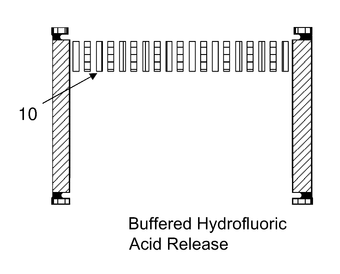
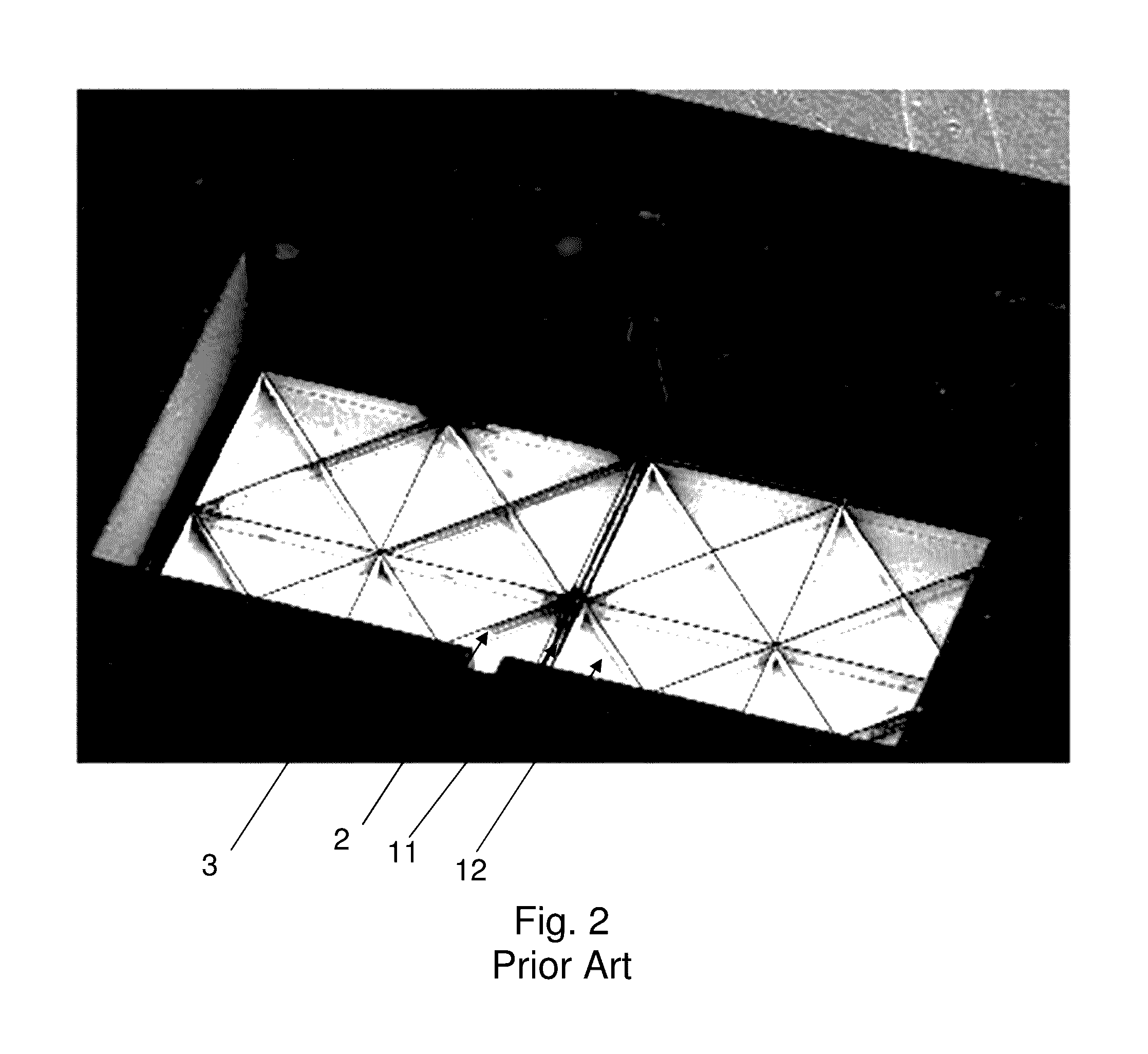
[0077]According to one embodiment of the technology, a 1 mm×2 mm microphone diaphragm is made of polysilicon and has stiffeners and carefully designed hinge supports to ensure that it responds like a rigid body on flexible hinges. Larger microphone diaphragms, e.g., 1 mm×3 mm are also possible. The diaphragm is designed to respond to pressure gradients, e.g., due to acoustic waves in air, giving it a first-order directional response to incident sound. Both the diaphragm and stiffening ribs are made of LPCVD (low pressure chemical vapor deposition) polysilicon. The diaphragm is about 2 μm thick and the stiffening ribs are 4 μm wide and 40 μm tall. This structure provides a highly compliant differential microphone that responds to the differences in pressure on the two sides of the diaphragm that are separated by the hinges at the center [4, 20-22]. Interdigitated fingers, which consist of 100 μm long, 1.5 μm wide fingers with 6 μm periodicity, are incorporated at the perimeter of the...


PUM


Abstract

A micromechanical structure, comprising a substrate having a through hole; a residual portion of a sacrificial oxide layer peripheral to the hole; and a polysilicon layer overlying the hole, patterned to have a planar portion; a supporting portion connecting the planar portion to polysilicon on the residual portion; polysilicon stiffeners formed extending beneath the planar portion overlying the hole; and polysilicon ribs surrounding the supporting portion, attached near a periphery of the planar portion. The polysilicon ribs extend to a depth beyond the stiffeners, and extend laterally beyond an edge of the planar portion. The polysilicon ribs are released from the substrate during manufacturing after the planar region, and reduce stress on the supporting portion.

Description

CROSS REFERENCE TO RELATED APPLICATION[0001]The present application is a Division of U.S. patent application Ser. No. 14 / 039,149, filed Sep. 27, 2013, now U.S. Pat. No. 9,181,086, issued Nov. 10, 2015, which is a non-provisional of, and claims benefit of priority from, U.S. Provisional Patent Application Ser. No. 61 / 708,282, filed Oct. 1, 2012, the entirety of which are expressly incorporated herein by reference.STATEMENT OF FEDERAL SUPPORT[0002]This invention was made with government support under awards R01 DC009859 and R01 DC009429 awarded by the National Institutes of Health. The government has certain rights in this invention.FIELD OF THE INVENTION[0003]The present invention relates to the field of micro-electro-mechanical system (MEMS) devices.BACKGROUND OF THE INVENTION[0004]Over the past twenty years researchers have created a nearly uncountable number of MEMS sensors and actuated structures using the tools of microfabrication. The scientific and engineering literature conta...

Claims


Application Information

Patent Timeline
Patent Type & Authority Patents(United States)
IPC IPC(8): H04R19/04B81C1/00B81B3/00
CPCH04R19/04B81B3/007B81B3/0027B81C1/00595B81B2201/0257B81B2203/0127B81B2207/053H04R2201/003H04R2307/025B81B2201/042
Inventor MILES, RONALD N.CUI, WEILI
Owner THE RES FOUND OF STATE UNIV OF NEW YORK
Why Eureka
Try Eureka