Fuel valve

a fuel valve and valve body technology, applied in the direction of packaging goods, combustion types, containers, etc., can solve the problems of large change in fire power, inability to vaporize, ball valves and regulator valves, etc., and achieve the effect of accurately adjusting the flow rate of fuel and simple structur

Active Publication Date: 2017-02-14
SHINFUJI BURNER CO LTD
View PDF26 Cites 0 Cited by
  • Summary
  • Abstract
  • Description
  • Claims
  • Application Information

AI Technical Summary

Benefits of technology

[0015]A first object of the present invention is to provide a fuel valve which is simple in structure and which can accurately adjust the flow rate of fuel to be supplied to a burner. A second object of the invention is to provide a fuel valve which makes it possible to produce flames which can sufficiently heat the burner during a preheating step.

Problems solved by technology

Especially if a liquid fuel is used as fuel for a burner and the fire power is adjusted by adjusting the flow rate of the liquid fuel, it is necessary to control the flow rate with high accuracy, because liquid fuel is expanded to 200 times or more of its original volume when vaporized, so that a slight change in the flow rate of liquid fuel can lead to a large change in fire power.
While it is necessary to vaporize liquid fuel in the vaporizer, while the vaporizer is not sufficiently heated immediately after the use of the burner, it cannot be vaporized.
Any of the above-mentioned needle valves, ball valves and regulator valves offers problems in stably adjusting the flow rate.
But it is practically impossible to infinitely reduce the thread pitch because the smaller the thread pitch, the lower the resistance to e.g. wear.
Thus, it is impossible to adjust the flow rate of liquid fuel in a sufficiently fine manner required for liquid fuel.
This complicates the entire device, increases the cost of the device, and makes it more difficult to operate the device.
But if a liquid fuel such as gasoline for motor vehicles is used, foreign matter such as soot tends to adhere to the inner wall of the orifice, thus clogging the orifice.
Since regulator valves are complicated in structure and made up of a large number of parts, they are expensive and less durable.
The preheating step in which liquid fuel impregnated in e.g. glass wool is burned is extremely troublesome for inexperienced users.
Flames produced during this preheating step are weaker in force than flames produced by the burner and can be shaken by the wind.
Thus, on a windy day, it is difficult to direct the flames produced during the preheating step at the burner (especially the vaporizer), thus making it difficult to sufficiently heat the vaporizer.

Method used


Image

  • Fuel valve
  • Fuel valve
  • Fuel valve

Examples


Embodiment Construction

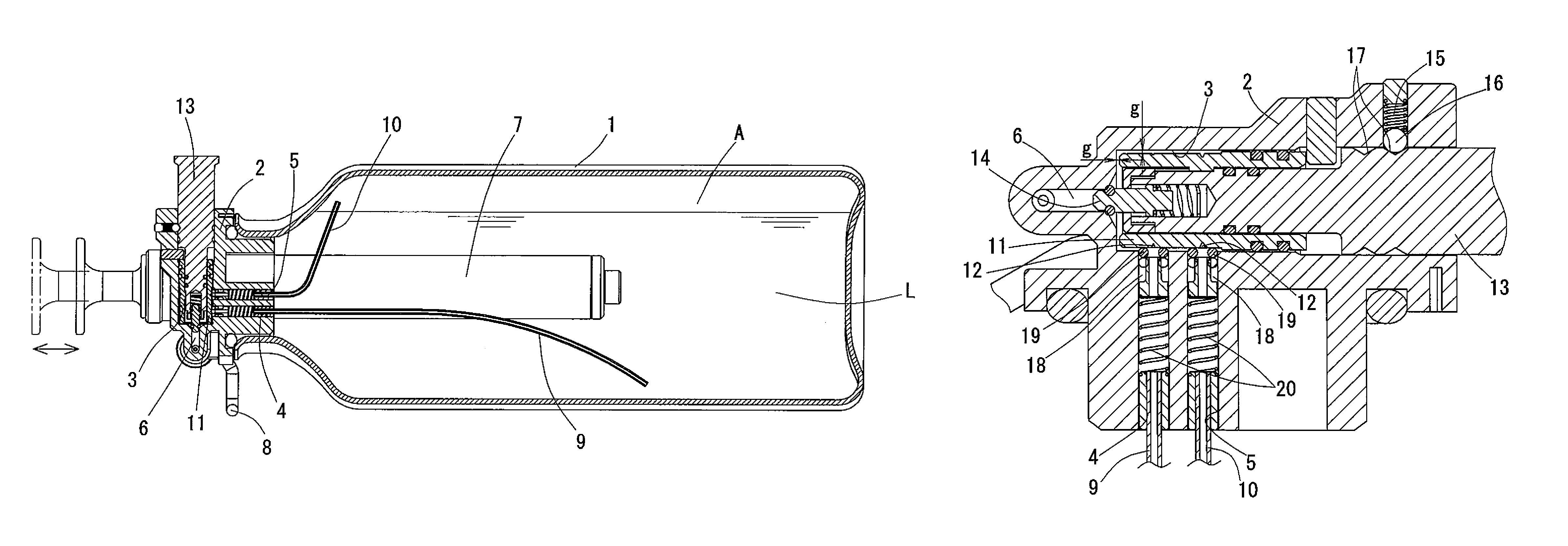
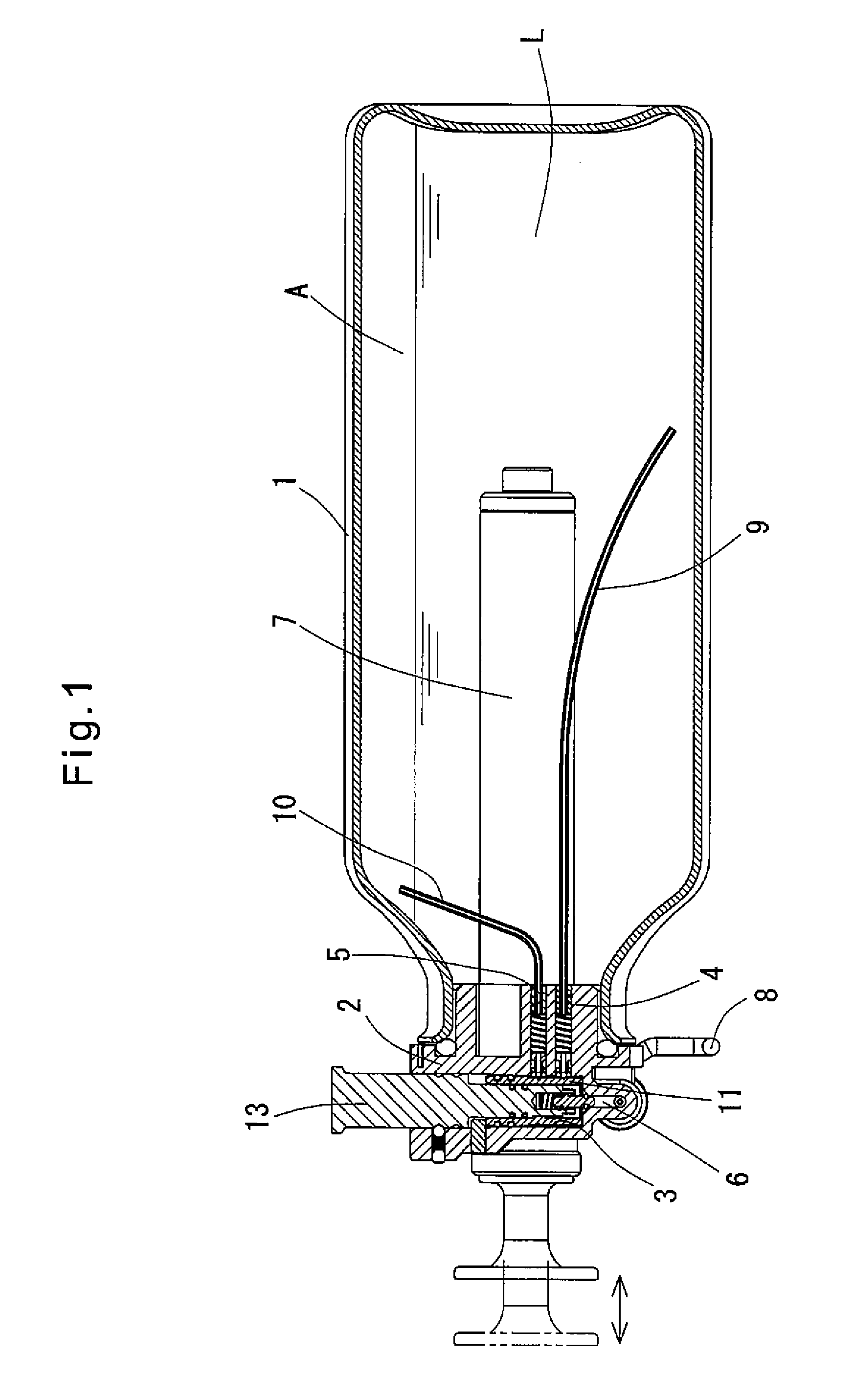
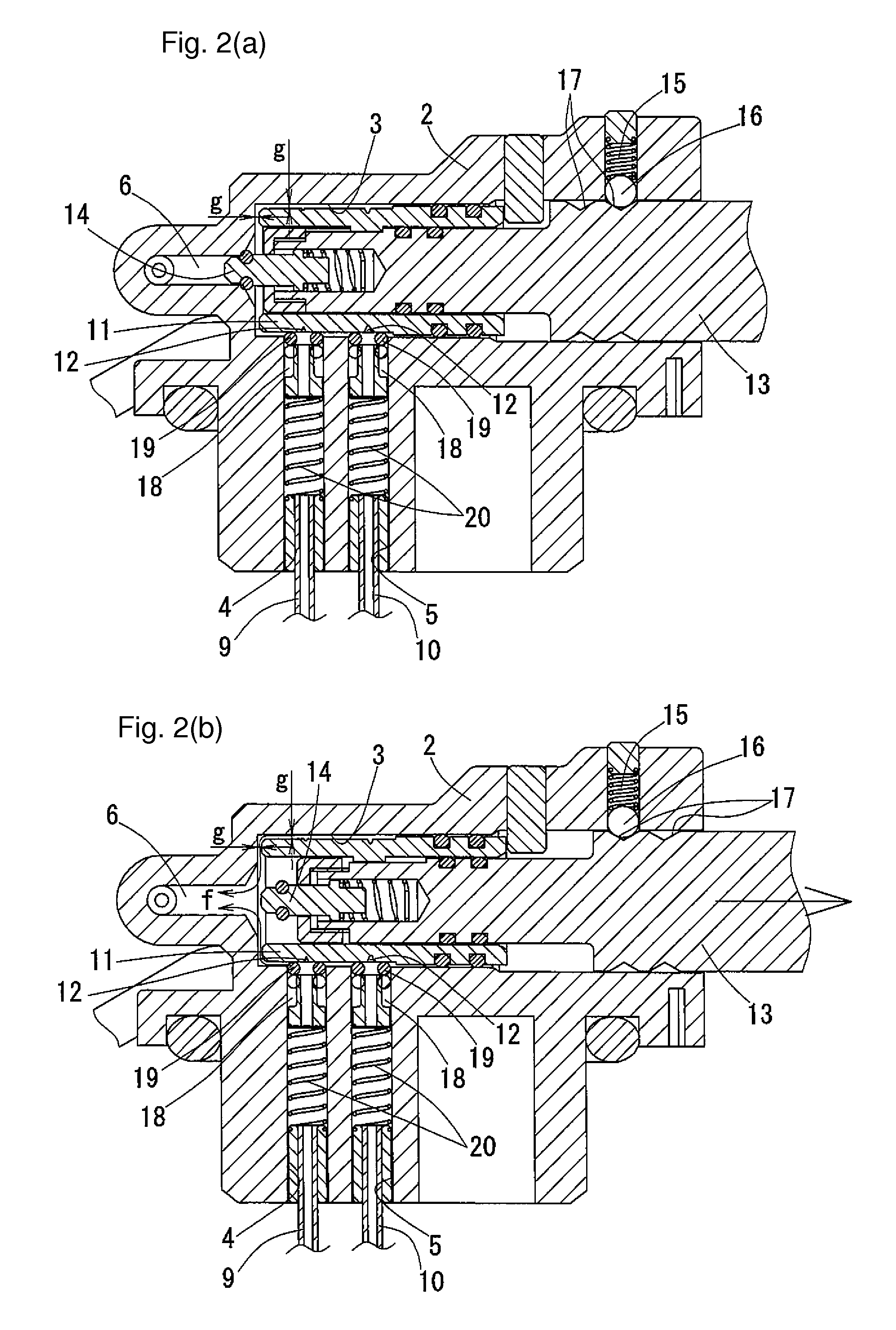
[0041]FIG. 1 shows a fuel tank including a fuel valve according to the present invention. FIGS. 2(a) and 2(b) show the fuel valve. The fuel valve is used to feed a liquid fuel L, such as gasoline or kerosene, in the tank 1 to a burner (not shown). The fuel valve is arranged in a horizontally extending position.

[0042]A cap 2 is fitted on the opening of the tank 1. The cap 2 defines a fuel mixing chamber 3, a liquid fuel passage 4, an air passage 5 and a fuel discharge port 6. Air is fed into the tank 1 by an air pump 7 to pressurize the interior of the tank 1. The tank 1 is held in the horizontal position by a stand 8.

[0043]A liquid fuel supply pipe 9 and an air supply pipe 10 are located in the tank 1. The liquid fuel supply pipe 9 has its first end (suction port) located in the liquid fuel L. The air supply pipe 10 has its first end (suction port) located in the air A in the tank. The liquid fuel supply pipe 9 and the air supply pipe 10 have their second ends (outlet ports) connect...


PUM

PropertyMeasurementUnit
flow ratesaaaaaaaaaa
depthaaaaaaaaaa
widthaaaaaaaaaa

Abstract

A fuel valve includes a cylindrical flow adjusting member having a cylindrical surface formed with two circumferentially extending V-shaped grooves for liquid fuel and air, respectively. The fuel valve further includes liquid fuel and air supply pipes having O-rings at their respective discharge ports which are kept in abutment with the cylindrical surface such that when the flow rate adjusting member is rotated to a position where the V-shaped grooves extend across and protrude from the respective O-rings, the discharge ports of the supply pipes communicate with the respective V-shaped grooves, so that liquid fuel and air flow. The depths, widths and positions of the respective V-shaped grooves are determined corresponding to an igniting position (preheating step), normal burning positions (high heat to low heat), and a discharge position such that the flow rates of liquid fuel and air can be adjusted in synchronization with each other.

Description

TECHNICAL FIELD[0001]This invention relates to a fuel valve for burners such as those used outdoors.BACKGROUND ART[0002]Typically, burners such as those used outdoors include a fuel tank (such as a portable fuel bottle) containing fuel, a burner head and a flow rate adjusting valve. Fuel in the tank is fed to the burner head through the flow rate adjusting mechanism and burned. Such burners include the type in which vaporized fuel is taken out of the fuel tank and burned, and the type in which liquid fuel is taken out of the fuel tank, vaporized in a vaporizer, and the thus vaporized fuel is burned.[0003]In order to control the flow rate of liquid fuel or vaporized fuel, a needle valve, a ball valve, or a regulator valve is ordinarily used.[0004]As disclosed in U.S. Pat. No. 4,575,043, needle valves include a valve box, and a needle shaft and a valve seat both mounted in the valve box, the needle shaft being formed with a thread on the outer periphery and having a tapered tip, and t...

Claims


Application Information

Patent Timeline
Patent Type & Authority Patents(United States)
IPC IPC(8): F17C13/06F23K5/02F23K5/14
CPCF17C13/06F23K5/02F23K5/147F23K2301/206F23N1/027F23D14/28F16K11/076F16K11/0856F23K2300/206F23K5/00
Inventor YAMAMOTO, HIROSHI
Owner SHINFUJI BURNER CO LTD
Why Eureka
Try Eureka