
Measurement and modeling of salinity contamination of soil and soil-water systems from oil and gas production activities

a technology of oil and gas production and salinity contamination, applied in the field of system and method of measuring and modeling salinity contamination of soils, can solve the problems of reducing the ability of plants to uptake water, destroying soil structure and permeability, and raising the sodicity of soil and potentially reducing soil textur

Active Publication Date: 2017-02-28
DTN LLC
View PDF2 Cites 5 Cited by
  • Summary
  • Abstract
  • Description
  • Claims
  • Application Information

AI Technical Summary

Benefits of technology

The present invention is a system and method for monitoring and assessing the risks associated with saltwater disposal from oil and gas drilling sites to the surrounding environment and the agricultural and environment impact on rangeland, cropland, and aquifers. It uses remote sensing platforms to detect and monitor the presence of saltwater in soils, and upon detection, assesses impact on vegetation, soil contamination, and the possibility of vertical and lateral movement of saltwater within soils. The invention can generate forecasts, predictions, and recommendations as downstream or follow-on services for landowners, farmers, oil and gas production site operators, governmental regulators, and other end users for contamination mitigation activities. Ultimately, the invention addresses the problem of salinity contamination in soils caused by oil and gas drilling activities.

Problems solved by technology

Salinity contamination of soils and aquifers from exposure to high amounts of saltwater can cause adverse and long lasting impacts as salt accumulates or disassociates, leaving sodium ion particles that raise the sodicity of soil and potentially reduce soil texture.
The accumulation of saltwater in soils can cause damage by destroying soil structure and permeability.
Seed germination may be reduced in the presence of high concentrations of soluble salts, which limit a plant's ability to uptake water.
With sufficient concentrations, salt-contaminated soil can lose its ability to support agricultural crops and other vegetation.
Over time this may further contribute to erosion.
Products extracted from a typical oil well involving hydraulic fracturing are crude oil and natural gas, along with the injected saltwater, which becomes an unwanted byproduct of the process.
There are significant challenges with managing SWD, as indicated by the current assessment of oil and gas production development in the North Dakota Bakken Formation.
With the need to store saltwater quantities of this magnitude at handling facilities and transfer those quantities to SWD wells, the risk for potential leakage or spillage into surrounding soils and aquifers is a major concern.
The greater risk of soil contamination, especially to rangeland and cropland, occurs both between the production location and a SWD site, and at the SWD site itself.
This can lead to significant long-term effects on soils, aquifers, rangeland, and cropland.
The unplanned release of saltwater brine resulting from truck and / or pipeline transport of brine, leakage from containment ponds associated with active oil and gas drilling, and at SWD sites presents a host of contamination problems with wide-ranging effects on soils, vegetation, crops, livestock, and people.
Further, if the infiltration is sufficient and sustained for a period of time, in extreme cases it can lead to a horizontal movement in soils resulting in an expansion in the contamination area and causing a wide-ranging impact cropland.
Under such situations this can also lead to the contamination of groundwater supplies and present a threat to drinking water for both humans and animals.
Episodes of excessive or prolonged precipitation can further exacerbate this problem if undetected.

Method used

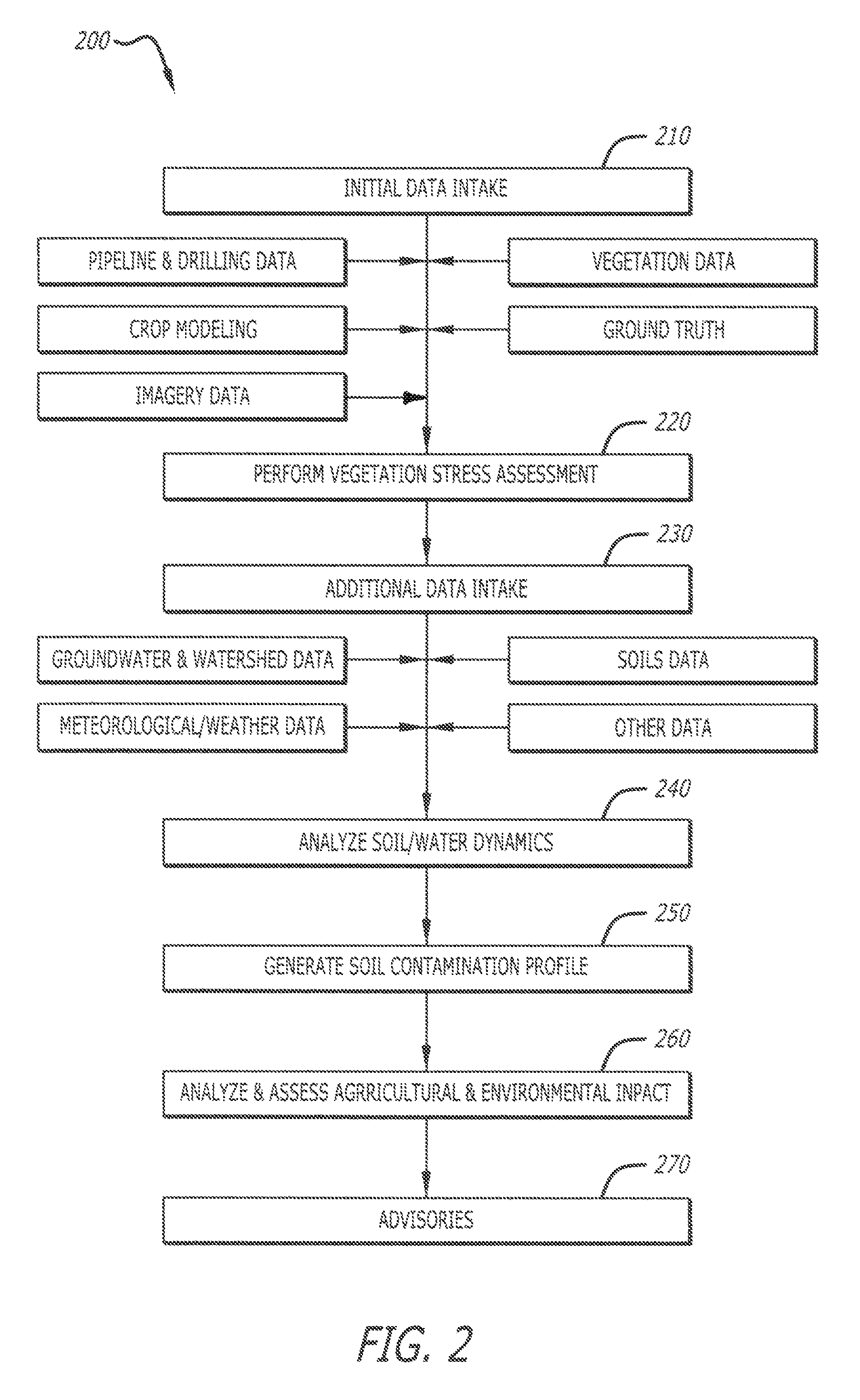

Image

  • Measurement and modeling of salinity contamination of soil and soil-water systems from oil and gas production activities
  • Measurement and modeling of salinity contamination of soil and soil-water systems from oil and gas production activities
  • Measurement and modeling of salinity contamination of soil and soil-water systems from oil and gas production activities

Examples


Embodiment Construction

[0015]In the following description of the present invention reference is made to the exemplary embodiments illustrating the principles of the present invention and how it is practiced. Other embodiments will be utilized to practice the present invention and structural and functional changes will be made thereto without departing from the scope of the present invention.

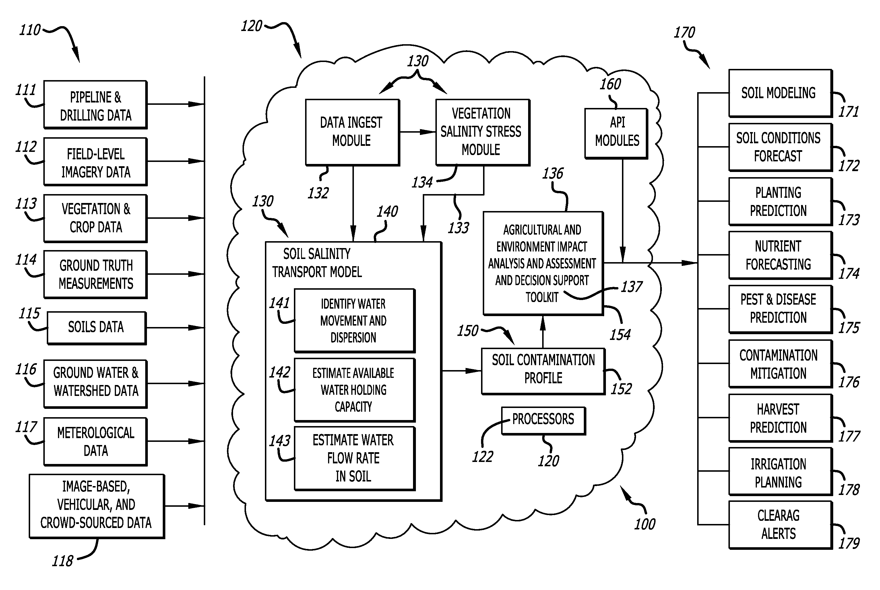
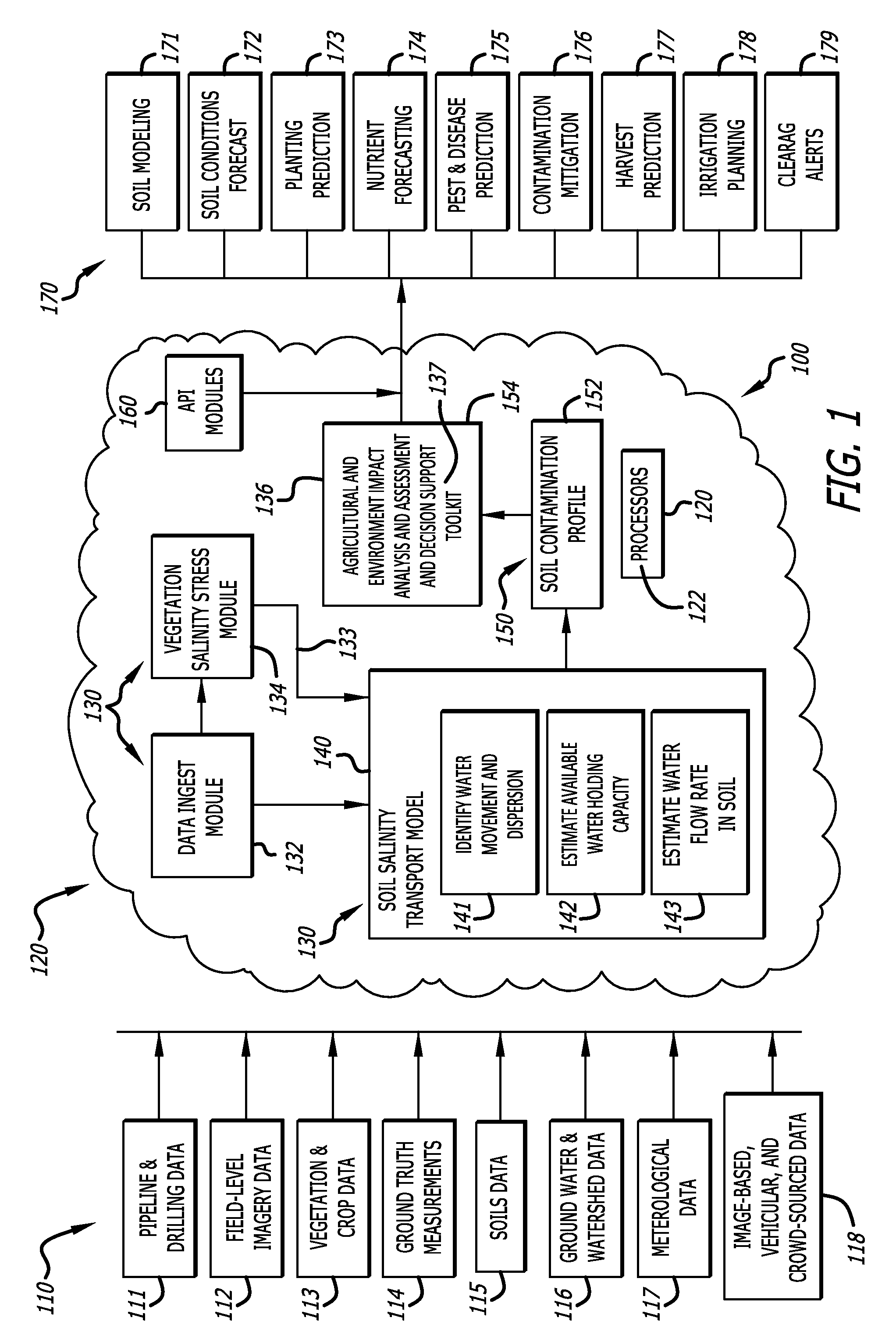
[0016]FIG. 1 is a diagram of system components in an analytical framework 100 for soil contamination detection, assessment and impact analysis according to the present invention. In this analytical framework 100, input data 110 is ingested from various sources for analysis in one or more data processing modules 130 within a computing environment 120. These data processing modules 130 are configured to receive, ingest, request, or otherwise obtain the data input data 110, perform a vegetation salinity stress assessment, and analyze both soil contamination from saltwater that is a by-product of oil and gas drilling opera...


PUM


Abstract

An analytical framework and modeling process for assessing salinity contamination of soil ecosystems in geographical areas related to oil and gas production sites combines detection and monitoring of unplanned saltwater releases from such production activities with soil impact prediction. The analytical framework and modeling process enables an assessment of risks associated with saltwater disposal from drilling operations to the surrounding environment and the impact on soils, aquifers, rangeland, cropland, and adjoining areas by monitoring water movement and other soil conditions, and generating predictive output data for landowners, farmers, oil and gas production site operators, governmental regulators, and other end users for contamination mitigation and agricultural activities.

Description

CROSS-REFERENCE TO RELATED APPLICATION(S)[0001]This patent application claims priority to U.S. provisional application 62 / 005,032, filed on May 30, 2014, the contents of which are incorporated in their entirety herein. In accordance with 37 C.F.R. §1.76, a claim of priority is included in an Application Data Sheet filed concurrently herewith.FIELD OF THE INVENTION[0002]The present invention relates to saltwater and / or sodium chloride contamination of soils and the surrounding environment. Specifically, the present invention relates to systems and methods of measuring and modeling salinity contamination of soils related to extracting carbons such as oil and gas from the earth.BACKGROUND OF THE INVENTION[0003]Salinity contamination of soils and aquifers from exposure to high amounts of saltwater can cause adverse and long lasting impacts as salt accumulates or disassociates, leaving sodium ion particles that raise the sodicity of soil and potentially reduce soil texture. The accumulat...

Claims


Application Information

Patent Timeline
Patent Type & Authority Patents(United States)
IPC IPC(8): G06G7/58B09C1/00
CPCB09C1/002
Inventor OSBORNE, LEON F.
Owner DTN LLC
Learn More