Measurement system

a measurement system and measurement technology, applied in the field of measurement systems, can solve problems such as the adverse effect of reflection light detection

Active Publication Date: 2017-03-28
PANASONIC INTELLECTUAL PROPERTY MANAGEMENT CO LTD
View PDF12 Cites 48 Cited by
  • Summary
  • Abstract
  • Description
  • Claims
  • Application Information

AI Technical Summary

Benefits of technology

[0006]One non-limiting and exemplary embodiment provides a measurement system that reduces an effect of ambient light and that is applicable to highly accurate measurement.

Problems solved by technology

When reflection light is detected, other light sources except for the irradiation light and ambient light such as sunlight have an adverse effect on the detection of the reflection light.

Method used


Image

  • Measurement system
  • Measurement system
  • Measurement system

Examples


first embodiment

[0064]Hereinafter, the structure and the function of TOF image pickup system 10A will be described with reference to FIGS. 1 and 2.

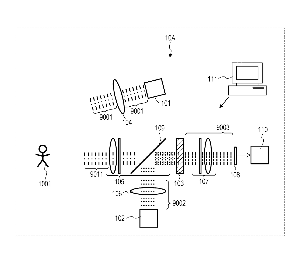
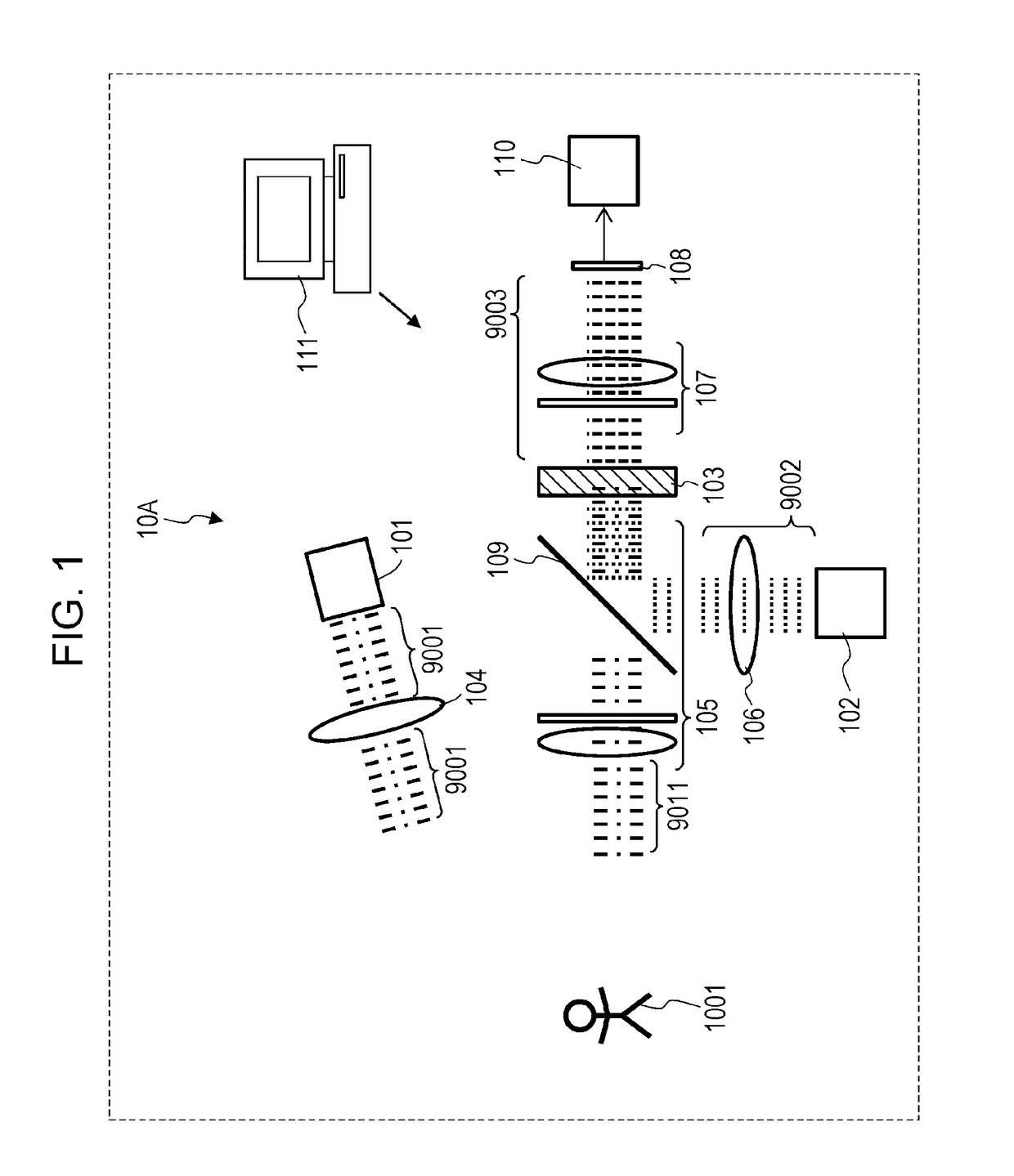
[0065]FIG. 1 schematically illustrates the configuration of the TOF image pickup system 10A according to the present embodiment. It is to be noted that this configuration diagram illustrates only the elements necessary to describe the present disclosure. Also, the configuration diagram is strictly a diagram illustrating the concept. The shape, aspect ratio, and scale of each element in reality are not taken into consideration at all.

[0066]The TOF image pickup system 10A includes a first light source 101, a second light source 102, a nonlinear optical crystal 103, a first optical system 104, a second optical system 105, a third optical system 106, a fourth optical system 107, an image sensor 108, an optical mixing element 109, a processor 110, and a controller 111. A light source unit includes the first light source 101 and the second light source 102. Th...

second embodiment

[0129]A TOF image pickup system 10B that uses pulsed light as irradiation light will be described with reference to FIGS. 4 to 7D.

[0130]FIG. 4 schematically illustrates the configuration of the TOF image pickup system 10B according to the present embodiment. Hereinafter, different points from the first embodiment will be mainly described and detailed description of similar points is omitted.

[0131]The first light source 101 generates the first intensity-modulated light 9001. The first light 9001 is treated as a train of impulses with a narrow pulse width that are emitted with a certain period.

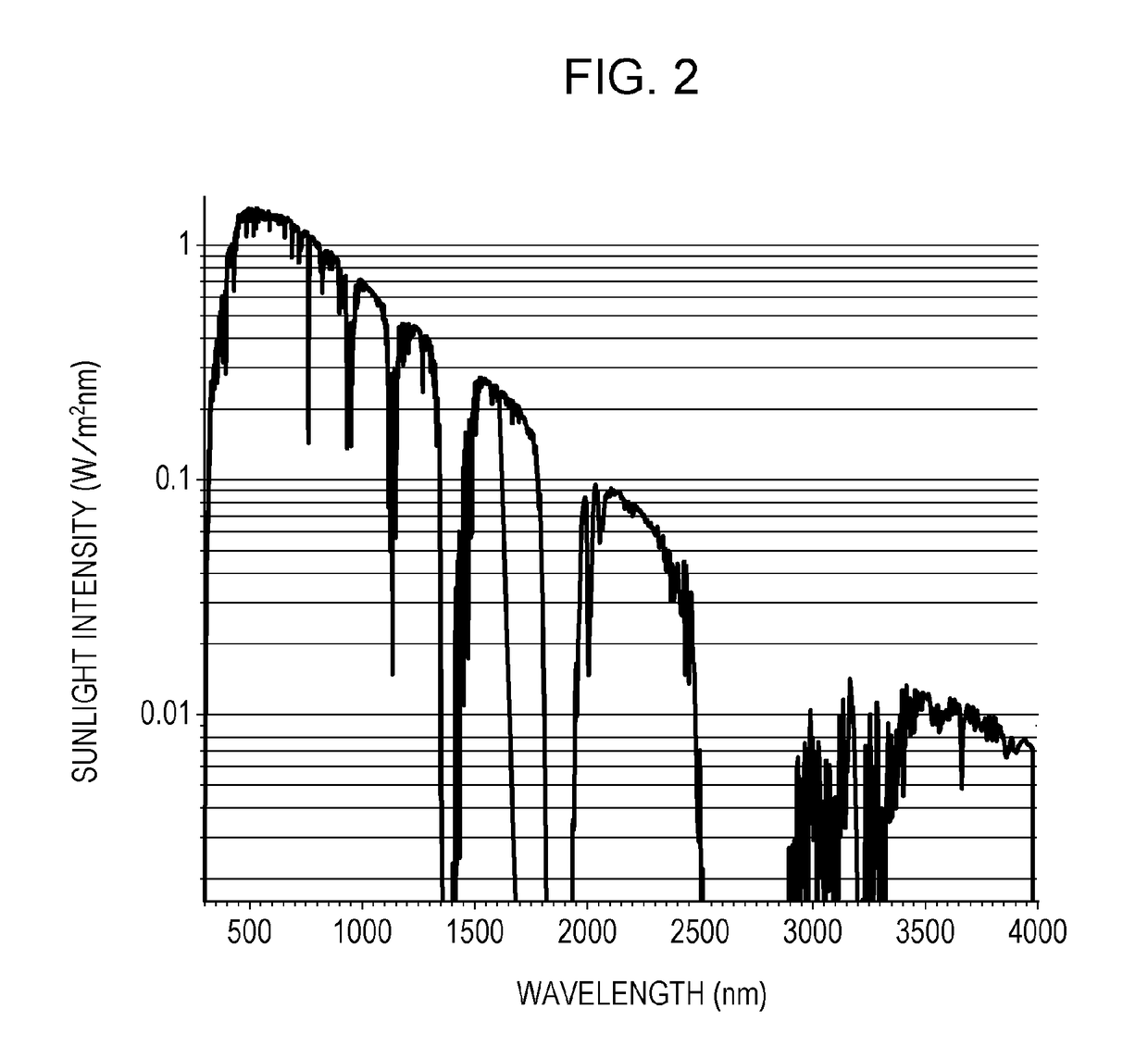
[0132]As described in the first embodiment, the wavelength of the first light 9001 may be selected freely. In the present embodiment, light with a wavelength of 1450 nm is utilized. The wavelength belongs to the sunlight lacking wavelength band and is an eye safe wavelength with which an image is not formed on the retina.

[0133]The object 1001 is irradiated with the first light 9001 using the fir...

third embodiment

[0164]An image pickup system 10C according to the present embodiment will be described with reference to FIGS. 9 to 12E. The image pickup system 10C has substantially the same configuration as that of the image pickup system 10A according to the first embodiment. In the present embodiment, efficient functioning of the image pickup system 10C in image pick-up in bad weather such as fog will be described.

[0165]FIG. 9 schematically illustrates the configuration of the image pickup system 10C according to the present embodiment. As illustrated, the object 1002 includes a fog 1041. The reflection light 9011 from the object 1002 includes reflection light 9311 from an object 1031 and reflection light 9411 from the fog. Hereinafter, it is assumed that the modulation of the second light 9002 is polarization modulation.

[0166]FIG. 10A illustrates the intensity of the first light 9001. FIG. 10B illustrates the intensity of the reflection light 9311 from the object. FIG. 10C illustrates the inte...


PUM

PropertyMeasurementUnit
wavelengthaaaaaaaaaa
wavelength rangeaaaaaaaaaa

Abstract

A measurement system, comprising: a first light source that generates first light and irradiates an object with the first light, at least one of an intensity, a polarization state, and a wavelength being modulated with a first period in the first light; a second light source that generates second light, at least one of an intensity, a polarization state, and a wavelength being modulated with a second period in the second light; a first optical system that mixes light from the object based on the first light with the second light; a nonlinear optical crystal that generates third light from the mixed light by sum-frequency generation phenomenon, the third light having a frequency equivalent to a sum of a frequency of the light from the object based on the first light and a frequency of the second light; and a photodetector that measures an intensity of the third light.

Description

BACKGROUND[0001]1. Technical Field[0002]The present application relates to a measurement system.[0003]2. Description of the Related Art[0004]A technique to visualize or a technique to detect a pedestrian and an obstacle (hereinafter may be referred to as an “object”) is important to improve the safety of automobiles. An image pickup system using a range gate camera is known as a representative instance. The range gate camera is a camera that is designed to have exposure (the gate is opened) only for an extremely short specific time. It is possible to pick up an image of only an object at a predetermined distance by a combination of a range gate camera and pulsed irradiation light. With a range gate camera, an adverse effect of a fog which is present in front of an object may be eliminated. A range gate camera also functions as a time of flight (TOF) image pickup system by successively changing gate opening timing. A range gate camera is disclosed in, for instance, in Mitsubishi Heav...

Claims


Application Information

Patent Timeline
Patent Type & Authority Patents(United States)
IPC IPC(8): G01J1/04G01S17/36G01S17/10G01S17/32G01S7/499G01S17/93G01S17/89G01S7/491G01S7/48G01S7/487G01S7/493G02F1/35G01S17/18G01S17/931
CPCG01J1/0407G01S7/4802G01S7/487G01S7/493G01S7/499G01S7/4917G01S17/10G01S17/107G01S17/32G01S17/36G01S17/89G01S17/936G02F1/3534G01S17/18G01S17/931
Inventor NOZAWA, KATSUYA
Owner PANASONIC INTELLECTUAL PROPERTY MANAGEMENT CO LTD
Why Eureka
Try Eureka