Integrated modular photovoltaic blanket assembly for space solar array

a solar array and solar array technology, applied in the field of solar arrays for spacecraft, can solve the problems of difficult rapid repair or re-configuration to a variety of planar aspect ratios, electrical subsystems, and one-piece blanket constructions that are not modular or reconfigurable, and achieve high quantity, high quality, and economic value.

Active Publication Date: 2017-04-11
DEPLOYABLE SPACE SYST
View PDF3 Cites 10 Cited by
  • Summary
  • Abstract
  • Description
  • Claims
  • Application Information

AI Technical Summary

Benefits of technology

[0010]The preferred embodiment of the present invention provides a modular flexible photovoltaic solar array panel assembly, termed Integrated Modular Blanket Assembly (IMBA), which can be economically manufactured in high quantity and with high quality, and can be rapidly assembled for operation and rapidly disassembled for expedient repair or replacement. The single most component within space solar arrays that is unequivocally the highest cost and most time consuming to manufacture is the solar panel assembly which is comprised of; Photovoltaic solar cells, interconnection of the solar cells, installation of protective glass on the frontside of the solar cells, interconnection of individual solar cells to form a circuit or string, and the laydown of that circuit onto a panel substrate through an adhesive bonding processes. The preferred invention that produces a photovoltaic flexible blankets assembly is comprised of separate but identical multiple standard power modules (SPM's). In the preferred embodiment the implementation of SPM's enables mass production at extraordinary low cost, and rapid assembly or changeout during integration and test activities. A discrete tension load bearing backplane, which is purposely not laminated to the SPM's, is directly coupled to the deployment structure and forms the planar surface onto which the SPM's are individually attached. Multiple discrete low profile fasteners secure the SPM's to the backplane by sandwiching the backplane between the fastener and the SPM. The fasteners can be readily connected or disconnected to rapidly assemble or remove the SPM's from the backplane. Electrical harnessing is routed along the backside of the backplane and connects to exposed circuit termination pads on either the frontside or rearside of the SPM. The preferred embodiment substantially reduces the amount of production time to build a flexible blanket solar array assembly from many months to days. The preferred embodiment provides the end-user lightweight, broad power range capability, high reliability, compact stowed volume, rollable or accordion foldable architectures, high stiffness, modularity, broad reconfiguration, high survivability within extreme thermal and plasma space environments, high quality, thermal stability, high voltage operability, and game-changing affordability.

Problems solved by technology

The prior art one-piece blanket construction is not modular or reconfigurable and presents difficulty for rapid repair or re-configuration to a variety of planar aspect ratios.
The fact that the delicate interconnected solar cells and circuits are in the load path presents a problem with respect to mechanical loading of the electrical subsystem which is not fundamentally designed to withstand significant loads.
In prior art systems the interconnected solar cells, strings and circuits are exposed to additional mechanical loading which hinder reliability and can cause opening of electrical circuits.
In addition to the aforementioned mechanical loading concerns within the electrical system, large thermal mismatches between the high thermal expansion polyimide based continuous blanket designs and the deployment structure are inherent drawbacks with these prior art flexible blanket solar arrays.
This deficiency degrades the total power output capability of the Harvey embodiment when operating within plasma environments.
The Harvey embodiment with its open backside surface does not allow for grouting, and as such is not an ideal design for high voltage operability and arc mitigation.
Another deficiency with the Harvey embodiment is that because the individual solar cells are bonded directly to the fiber reinforced substrate, whereby the fiber reinforced substrate is the tension load bearing structure, the interconnected solar cell circuits become exposed to unwanted mechanical and thermal stresses during operation in the deployed state, which in turn greatly reduces the solar cell circuits fatigue life and more likely would promote an open circuit condition rendering power loss to the spacecraft.
Yet another deficiency of the Harvey embodiment is the large amount of exposed silicone material that is coated on the panel assembly backside, which is problematic for the end-user and a major source of contamination from volatile outgassing.
Finally, the Harvey embodiment is not modular and is not produced from standard power modules (SPM's), but rather each individual solar cell is integrated to the blanket assembly as an independent component and not a higher level assembly.
This produces a rather labor intensive construction of the Harvey embodiment which does not promote affordability.
The weakness of the Kurland embodiment is that blanket tension loads are transferred through the delicate and low strength Kapton / polyimide film material.
This material has been known to structurally degrade and tear over a mission life making the application of this material as a structural member for a tensioned membrane flexible blanket not ideal.
As such, this material as the primary load bearing membrane has been known to tear and rip sometimes resulting in catastrophic failure.
Additionally, the Kapton / polyimide material has very high coefficient of thermal expansion and as such produces rather large dimensional instability on-orbit.
Finally, the Kurland embodiment is not modular and is not produced from standard power modules (SPM's), but rather each individual solar cell is integrated to the blanket assembly as an independent component and not a higher level assembly.
This produces a rather labor intensive construction of the Kurland embodiment which does not promote affordability.
Finally, the Maas embodiment is not modular and is not produced from standard power modules (SPM's), but rather each individual solar cell is integrated to the blanket assembly as an independent component and not a higher level assembly.
This produces a rather labor intensive construction of the Kurland embodiment which does not promote affordability.
Current processes for solar cell panel construction involve very labor intensive operations and many solar cell panels produced for space missions are custom constructions of differing panel geometries, solar cell and string features, and technologies.
Current and prior art solar panel designs are also not modular, making it difficult to mass produce with economical automation processes or even traditional labor intensive processes.
Additionally, with current solar panel technologies if one part is imperfectly produced it affects a larger part of the entire solar array system which must be reworked at considerable cost and schedule to the program.
Current solar array panel technology does not have modular construction and repair and rework are cumbersome and expensive.

Method used


Image

  • Integrated modular photovoltaic blanket assembly for space solar array
  • Integrated modular photovoltaic blanket assembly for space solar array
  • Integrated modular photovoltaic blanket assembly for space solar array

Examples


Embodiment Construction

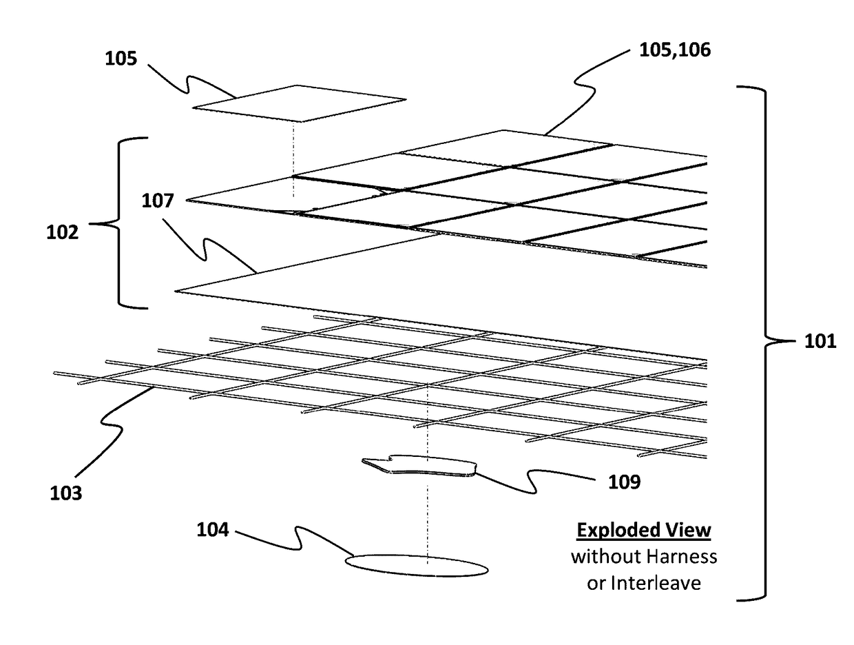
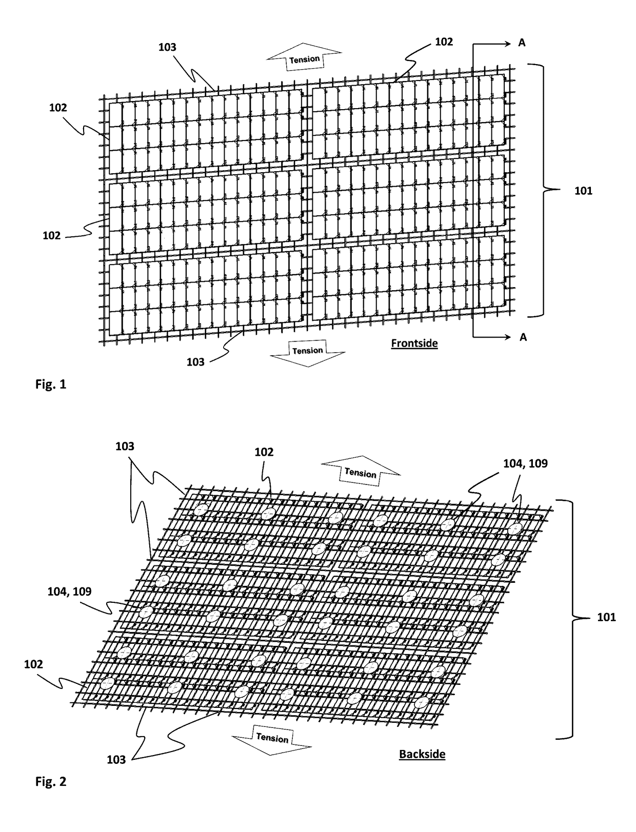
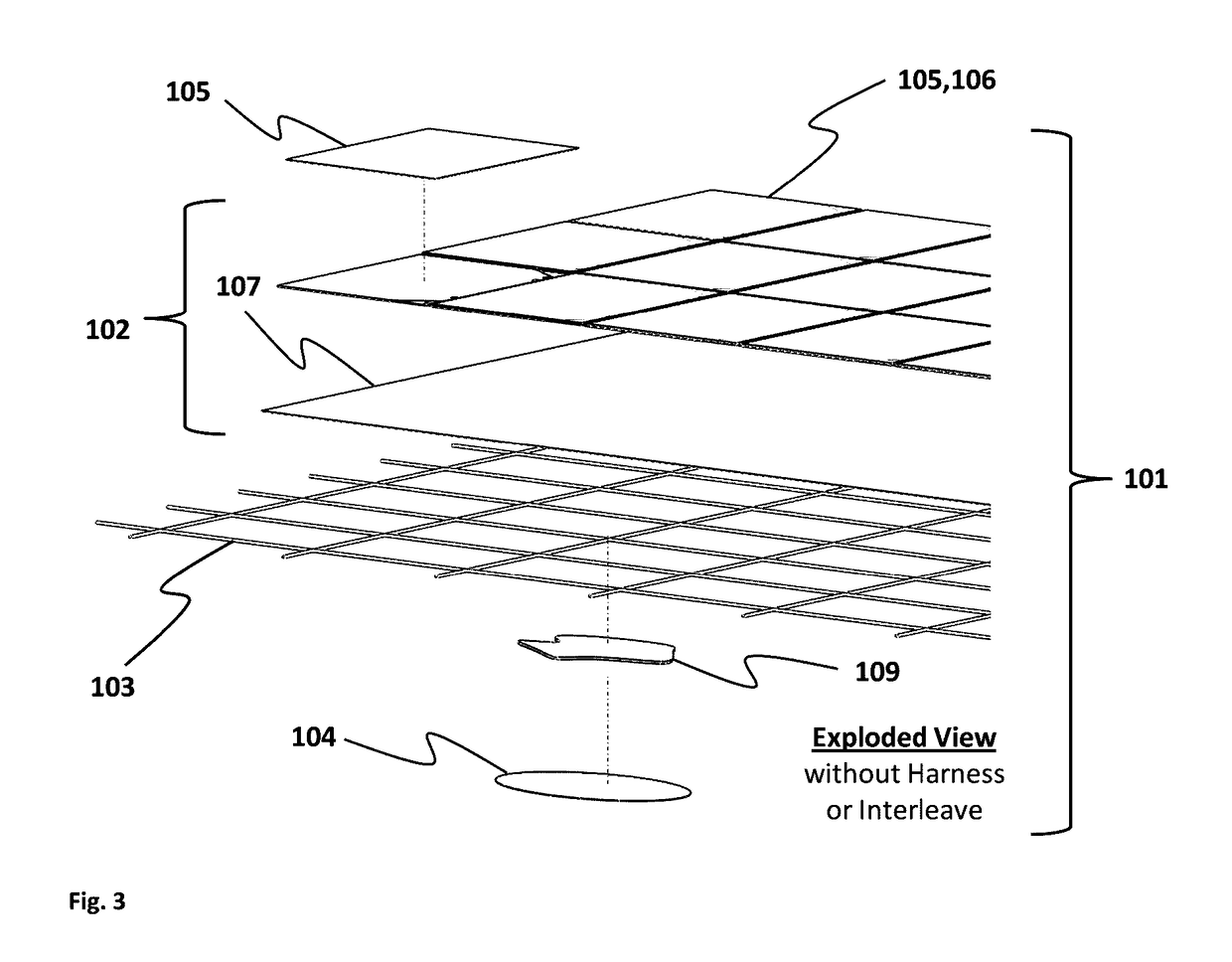
[0043]A flexible integrated modular photovoltaic blanket assembly (101) for a solar array is disclosed. In a preferred embodiment the technology is an accordion foldable or rollable flexible photovoltaic solar panel blanket assembly (101) for a spacecraft comprising a plurality of common photovoltaic standard power modules (102) spaced in an orthogonal array. The modules are mechanically attached with multiple low profile fasteners (104, 109) on their backside to a tensioned continuous surface backplane structure (103) such that the backplane (103) structure is sandwiched between the modules (102) and multiple low profile fasteners (104, 109). Each module (102) comprises a rectangular substrate with solar cell assemblies (105, 106) laid onto the substrate (107). The substrate (107) includes circuitry for incorporating the solar cells into a circuit. The module (102) includes a pair of extended electrical leads carrying circuit connections for the circuitry that provide connections t...


PUM


Abstract

A modular, lightweight, high-survivable, photovoltaic flexible blanket assembly for a space solar array is disclosed. The modular blanket is an accordion foldable or rollable flexible photovoltaic solar panel blanket assembly comprising a plurality of common photovoltaic modules spaced in an orthogonal pattern. Each module is mechanically attached with multiple low profile fasteners on their backside to an open weave mesh tensioned backplane structure. The backplane forms a tensioned dimensionally stable planar surface in the deployed configuration onto which the modules are suspended. Each module is common and comprised of a rectangular substrate that includes solar cell assemblies, circuitry, exposed electrical contacts for integration of blanket-level harnessing, and frontside and rearside shielding and coatings as required for the mission application. The blanket assembly may be dispersed with an open pattern of compliant and formable material on the backside to provide insulation against the vigorous vibration of the launch environment.

Description

FIELD OF THE INVENTION[0001]The present invention relates to solar cell arrays for use on spacecraft and, in particular, solar cell arrays comprised of a photovoltiac flexible blanket panel assembly consisting of integrated common photovoltaic standard power modules for powering spacecraft during long life space missions.BACKGROUND AND PRIOR ART[0002]Spacecraft most commonly use photovoltaic solar cells to collect solar radiation and convert it into the electrical power necessary to operate the spacecraft. The solar cells are normally disposed on a solar array system. A solar array typically comprises one or more solar panels mechanically and electrically attached to each other and to the spacecraft. Each solar panel in an array typically comprises numerous individual photovoltaic solar cells, which are usually laid out in rows and connected together electrically at their adjacent edges. Most deployable solar arrays for spacecraft have used crystalline solar cells mounted to rigid h...

Claims


Application Information

Patent Timeline
Patent Type & Authority Patents(United States)
IPC IPC(8): H01L31/044H02S30/20H01L31/041
CPCH01L31/045Y02E10/50H01L31/041H02S20/00B64G1/222B64G1/443H02S30/20
Inventor SPENCE, BRIAN RWHITE, STEPHEN FDOUGLAS, MARK VSCHMID, KEVIN BTAKEDA, RON S
Owner DEPLOYABLE SPACE SYST
Why Eureka
Try Eureka