Light emitting element and method for maufacturing light emitting element

a technology of light emitting elements and manufacturing methods, which is applied in the direction of basic electric elements, electrical devices, semiconductor devices, etc., can solve the problems of difficult to obtain the adhesive force improvement effect, insufficient sealing performance, and deterioration of the element, so as to achieve excellent light extraction efficiency, sufficient sealing performance, and deterioration of the organic layer.

Inactive Publication Date: 2017-05-23
JX NIPPON OIL & ENERGY CORP
View PDF43 Cites 10 Cited by
  • Summary
  • Abstract
  • Description
  • Claims
  • Application Information

AI Technical Summary

Benefits of technology

[0007]It is known that the frame sealing performed for the organic EL element having the diffraction grating substrate has the following problem. Namely, moisture and oxygen penetrate through a fine or minute concave-convex layer exposed to the outside of the sealed space, which results in deterioration of the element. Thus, in Japanese Patent Application Laid-open No. 2012-174410, the minute concave-convex layer is positioned within the sealed space. In this method, however, the sealing adhesive adheres not to the surface of the minute concave-convex layer but rather to a flat substrate surface, and thus it is difficult to obtain the adhesive force improving effect which would be otherwise brought about by the surface area increasing effect and the catching effect of the concave-convex surface of the minute concave-convex layer. Having no adhesive force improving effect may lead to insufficient sealing performance to cause the deterioration of the light emitting element, or may lead to insufficient adhesion between the adhesive and the substrate to cause the exfoliation (peeing off) of the adhesive after the sealing. An object of the present invention is to provide a light emitting element which includes a concave-convex structure layer functioning as a diffraction grating and a light emitting part which is sealed by frame sealing (frame-sealed) with sufficient sealing performance, thereby preventing the deterioration of the service life of the light emitting element, and a method for manufacturing the light emitting element.
[0049]The light emitting element of the present invention includes the concave-convex structure layer functioning as a diffraction grating, and thus light extraction efficiency thereof is excellent. Further, a light emitting part is sealed by frame sealing with sufficient sealing performance, and thus deterioration of the organic layer (light emitting part) due to moisture and oxygen is prevented and the light emitting element of the present invention has a long service life. Therefore, the light emitting element of the present invention is very useful in various devices such as displays and illumination devices.

Problems solved by technology

Namely, moisture and oxygen penetrate through a fine or minute concave-convex layer exposed to the outside of the sealed space, which results in deterioration of the element.
In this method, however, the sealing adhesive adheres not to the surface of the minute concave-convex layer but rather to a flat substrate surface, and thus it is difficult to obtain the adhesive force improving effect which would be otherwise brought about by the surface area increasing effect and the catching effect of the concave-convex surface of the minute concave-convex layer.
Having no adhesive force improving effect may lead to insufficient sealing performance to cause the deterioration of the light emitting element, or may lead to insufficient adhesion between the adhesive and the substrate to cause the exfoliation (peeing off) of the adhesive after the sealing.

Method used


Image

  • Light emitting element and method for maufacturing light emitting element
  • Light emitting element and method for maufacturing light emitting element
  • Light emitting element and method for maufacturing light emitting element

Examples


example 1

[0188]A mold having a concave-convex surface was manufactured as follows. At first, there was prepared a block copolymer produced by Polymer Source Inc., which was made of polystyrene (hereinafter referred to as “PS” in an abbreviated manner as appropriate) and polymethyl methacrylate (hereinafter referred to as “PMMA” in an abbreviated manner as appropriate) as described below.[0189]Mn of PS segment=868,000[0190]Mn of PMMA segment=857,000[0191]Mn of block copolymer=1,725,000[0192]Volume ratio between PS segment and PMMA segment (PS:PMMA)=53:47[0193]Molecular weight distribution (Mw / Mn)=1.30[0194]Tg of PS segment=96° C.[0195]Tg of PMMA segment=110° C.

[0196]The volume ratio between the first polymer segment and the second polymer segment (the first polymer segment: the second polymer segment) in the block copolymer was calculated on the assumption that the density of polystyrene was 1.05 g / cm3 and the density of polymethyl methacrylate was 1.19 g / cm3. The number average molecular wei...

example 2

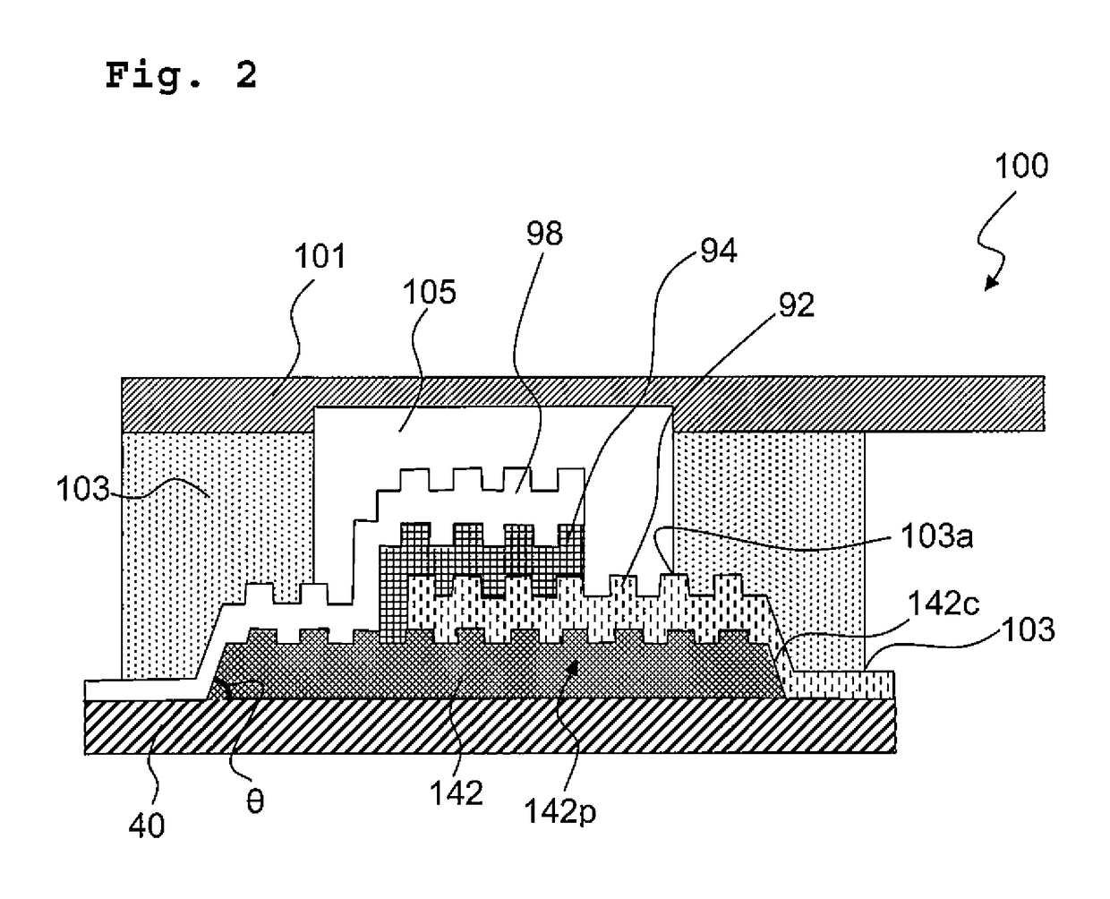
[0212]In Example 1, the resist pattern was formed to perform the patterning of the concave-convex structure layer by means of photolithography using the positive resist. In Example 2, the method for forming the resist pattern was changed as described below, and along with this, the method for stripping the resist was also changed. A light emitting element was manufactured in a similar manner to Example 1 except for the above. FIG. 2 schematically depicts a cross-sectional structure of the light emitting element manufactured in Example 2.

[0213]A negative resist prepared as described below was used as the resist. Namely, 100 parts of methacrylic acid-methyl methacrylate copolymer in which the composition ratio (molar ratio) of methacrylic acid and methyl methacrylate was 20:80 and the weight average molecular weight thereof was 30,000; 6 parts of pentaerythritol tetraacrylic ester; 2 parts of Michler's Ketone; and 2 parts of 4-(4-dimethylaminophenylazo)-phenol were dissolved in 330 pa...

example 3

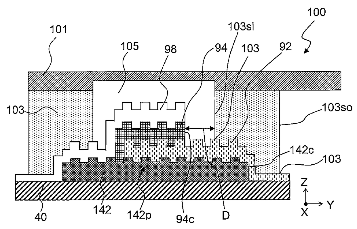
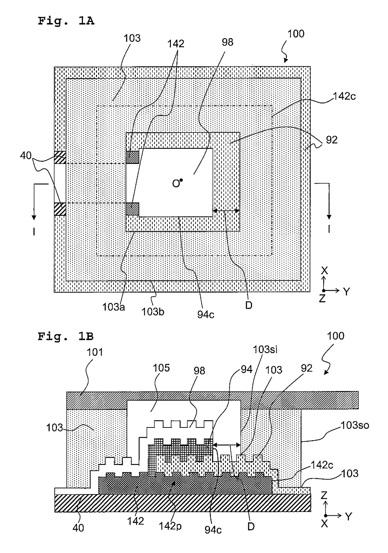
[0215]A light emitting element was manufactured in a similar manner to Example 1 except that the concave-convex structure layer was formed as described below by the UV curing method using a UV curable resin instead of the lift-off method. FIGS. 1A and 1B schematically depict a planer structure and a cross-sectional structure of the manufactured light emitting element, respectively.

[0216]1 g of silane coupling agent (KBM-5103 produced by SHIN-ETSU CHEMICAL, CO., LTD.) was added dropwise to a mixture of 1 g of water, 19 g of IPA, and 0.1 mL of acetic acid while the mixture was being stirred. After that, this mixture solution was stirred for another hour, thereby preparing a solution of the silane coupling agent. The base member was cleaned in a similar manner to Example 1, and then moisture on a surface of the base member was removed by drying using spin coater. The surface of the base member after the drying was coated with the solution of the silane coupling agent by spin coating. T...


PUM


Abstract

A light emitting element includes a base member, a sealing member disposed to face the base member, a concave-convex structure layer, a first electrode, an organic layer, a second electrode, and an adhesive layer. The concave-convex structure layer, the first electrode, the organic layer, and the second electrode are formed on the base member in that order. The adhesive layer is positioned between the base member and the sealing member. An outer periphery of the concave-convex structure layer is positioned between an inner periphery and an outer periphery of the adhesive layer. The light emitting element includes the concave-convex structure layer functioning as a diffracting grating, and thus light extraction efficiency thereof is excellent. Further, a light emitting part is sealed with sufficient sealing performance and deterioration of the light emitting part due to moisture and oxygen is prevented. Thus, the light emitting element has a long service life.

Description

CROSS REFERENCE TO RELATED APPLICATION[0001]This application is a continuation application of International Patent Application No. PCT / JP2014 / 071142 filed on Aug. 11, 2014 claiming the benefit of priority of Japanese Patent Application No. 2013-168700 filed on Aug. 14, 2013. The contents of International Patent Application No. PCT / JP2014 / 071142 and Japanese Patent Application No. 2013-168700 are incorporated herein by reference in their entities.BACKGROUND OF THE INVENTION[0002]Field of the Invention[0003]The present invention relates to a light emitting element and a method for manufacturing the light emitting element.[0004]Description of the Related Art[0005]Light emitting elements expected as next-generation of displays or illumination devices include an organic EL element (organic Electro-Luminescence element or organic light emitting diode). In the organic EL element, a hole injected from a hole injecting layer and electron injected from an electron injecting layer are carried ...

Claims


Application Information

Patent Timeline
Patent Type & Authority Patents(United States)
IPC IPC(8): H01L51/52
CPCH01L51/5253H01L51/5246H01L51/5268H10K50/813H10K50/822H10K50/8426H10K50/858H10K50/844H10K50/854
Inventor FUKUDA, MAKINISHIMURA, SUZUSHITORIYAMA, SHIGETAKASEKI, TAKASHI
Owner JX NIPPON OIL & ENERGY CORP
Why Eureka
Try Eureka