Dimmer holding current control circuit for phase cut dimming power supply

a control circuit and power supply technology, applied in the direction of lighting equipment, electrical equipment, light sources, etc., can solve the problems of front phase cut noise (leading edge), and achieve the effects of low cost, low heat radiation, and simple circui

a control circuit and power supply technology, applied in the direction of lighting equipment, electrical equipment, light sources, etc., can solve the problems of front phase cut noise (leading edge), and achieve the effects of low cost, low heat radiation, and simple circui

US9661710B1Active Publication Date: 2017-05-23ZHUHAI SHENGCHANG ELECTRONICS CO LTD

Image

  • Dimmer holding current control circuit for phase cut dimming power supply
  • Dimmer holding current control circuit for phase cut dimming power supply

Examples


Embodiment Construction

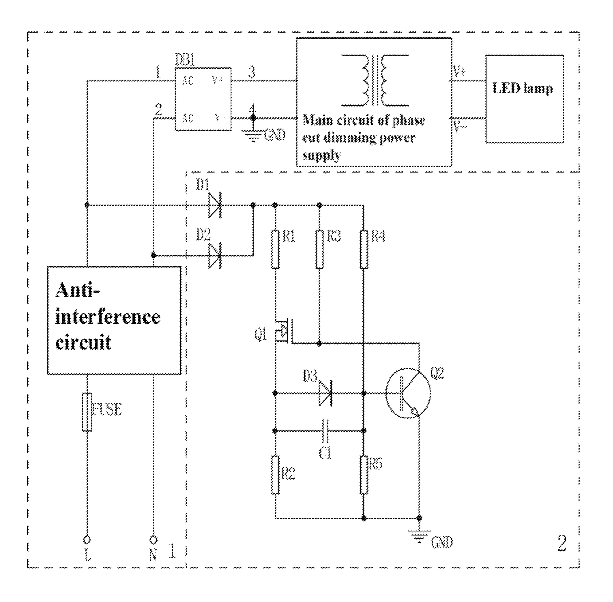
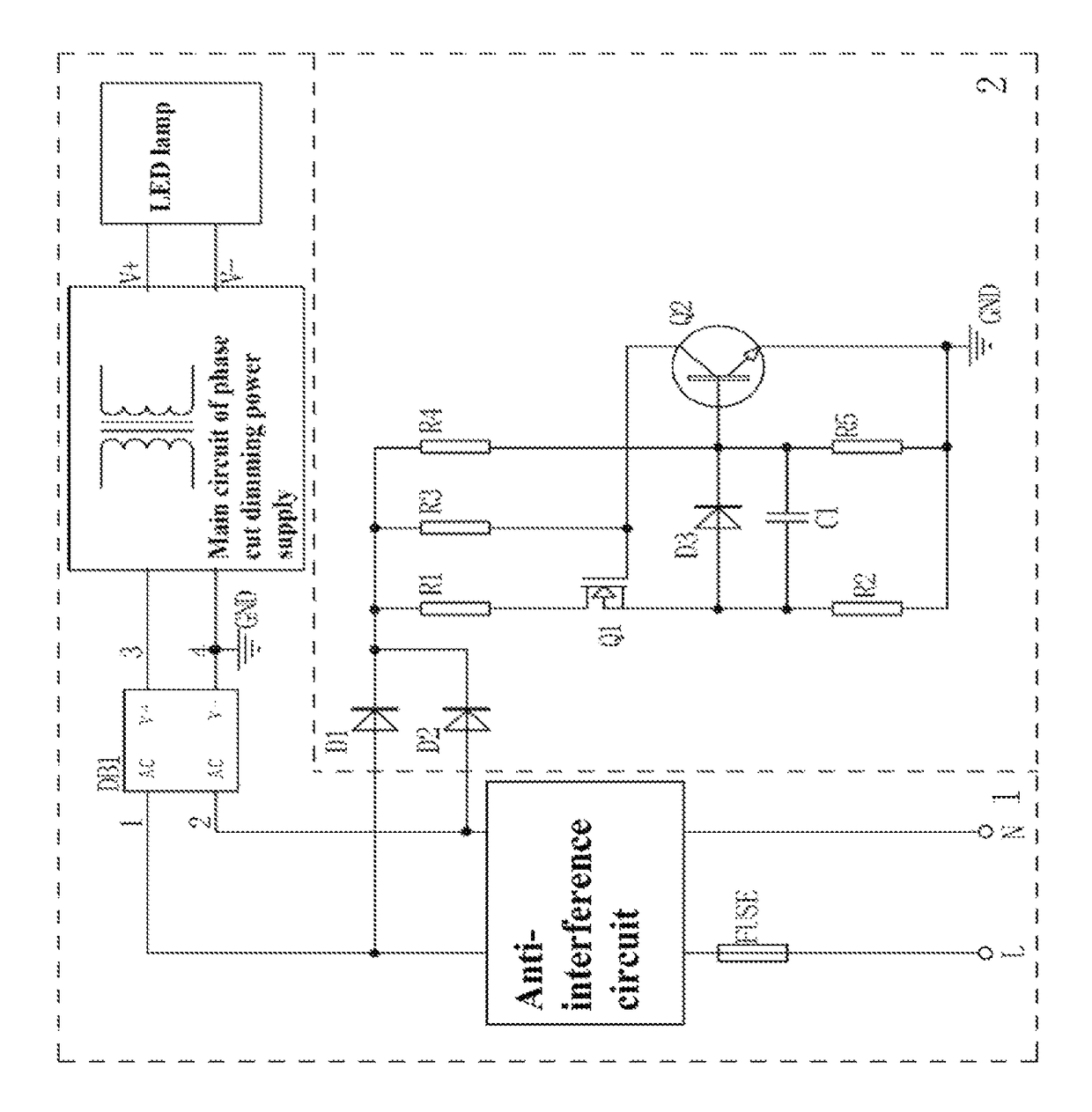
[0010]As shown in FIG. 1, the invention comprises phase cut dimming power supply circuit and LED lamp 1 and dimmer holding current control circuit 2. The phase cut dimming power supply circuit and LED lamp 1 is composed of an anti-interference circuit, a bridge rectifier, a main circuit of the phase cut dimming power supply and LED lamp, which are connected in turn. The anti-interference circuit is connected to L terminal and N terminal of main supply through a fuse. Dimmer holding current control circuit 2 is composed of rectifier diode I D1, rectifier diode II D2, field-effect transistor Q1, triode Q2, current-limiting resistance I R1, current-limiting resistance II R2, sampling resistance I R4, sampling resistance II R5, diode D3, capacitance C1 and resistance R3. The anodes of rectifier diode I D1 and rectifier diode II D2 are respectively connected to L terminal and N terminal of main supply input of the phase cut dimming power supply. The cathode of rectifier diode I D1 and th...


PUM


Abstract

The Invention discloses and provides a kind of dimmer holding current control circuit for phase cut dimming power supply, which comprises phase cut dimming power supply circuit and LED lamp (1) and dimmer holding current control circuit (2). The dimmer holding current control circuit (2) is composed of rectifier diode I (D1), rectifier diode II (D2), field-effect transistor (Q1), triode (Q2), current-limiting resistance I (R1), current-limiting resistance II (R2), sampling resistance I (R4), sampling resistance II (R5), diode (D3), capacitance (C1) and resistance (R3). The anodes of the rectifier diode I (D1) and the rectifier diode II (D2) are respectively connected to L terminal and N terminal of main supply input. The Invention makes the current small and stable through current limitation. The Invention can be widely used in the field of phase cut dimming power supply.

Description

FIELD OF THE INVENTION[0001]The Invention relates to the field of phase cut dimming, and more particularly relates to a kind of control circuit of the cut phase (silicon controlled) dimming power supply to provide holding current to the phase cut dimmer.BACKGROUND[0002]In the application of the phase cut dimming power supply, in order to produce good dimming effect, it is necessary for the phase cut dimming power supply to provide the transistor in the phase cut dimmer with a current to maintain a conducting state. Such a current should be stable, but not excessive, as excessive current requires more power consumption and reduces the overall conversion efficiency of the power supply.[0003]At present, what is used most is to connect an X capacitance (or thin-film capacitor) and a bleeder resistance to the input terminal of the power supply or connect an X capacitance (or thin-film capacitor) and then serial in a DM (differential mode) inductor in the front of such an X capacitance, t...

Claims


Application Information

Patent Timeline
23 May 2017
Publication
US9661710B1
IPC
H05B33/08; H05B37/02; H05B44/00
CPC
H05B33/0845; H05B37/02; H05B47/10; H05B45/10
Inventors
ZHENG, DEHUA; ZHAO, XIANYUN