Catheter system and intravascular blood pump comprising said catheter system

a catheter system and catheter technology, applied in the field of catheter systems, can solve the problems of physician failure, catheter can jam and bend back on itself, and the kinking is not always perceptible to the treating physician,

Active Publication Date: 2017-06-06
ABIOMED EURO
View PDF4 Cites 49 Cited by
  • Summary
  • Abstract
  • Description
  • Claims
  • Application Information

AI Technical Summary

Benefits of technology

[0011]The special advantage of employing an optical fiber as a kink sensor is that an optical fiber is of simple structure and accordingly cheap to manufacture, and that it in particular enables a kinking over the total length range of the catheter in which the optical fiber is laid. Conversely, a specific part of the catheter, such as the catheter tip, can also be designed to be especially kink-sensitive, so that kinking is detected preferably there.
[0014]The employment of an optical fiber as a kink sensor is accordingly very reliable. It is important, however, that the optical fiber itself does not break when a kink event occurs. In the case of plastic fibers, stress whitenings can occur, and in the case of glass fibers, the fibers as a whole can break. This, too, would in effect be correctly identified as a kink event by the evaluation device. However, the kink sensor would then be destroyed and no longer usable. To ensure continuing operability after extreme kink events, it is hence advantageous to configure optical fibers made of plastic with a diameter of 250 .mu.m or less. If the optical fiber comprises a glass fiber, the diameter of the optical fiber should amount to no more than 150 .mu.m. The stated diameter values respectively relate to the total diameter of the optical fiber including any coatings of the light-transmitting optical-fiber core. Breaks and also stress whitenings of the fibers can likewise be detected. This makes it possible to notify the user of the failure of the measurement device and thus avoid further placement attempts being made with a defective system. This is important for use as a medical sensor.
[0020]At the same time, the kink sensor can also extend beyond the catheter along the blood pump, for example to the distal end of the blood pump. This is expedient for example in cases where the blood pump possesses at its distal end a flexible flow cannula which is itself in danger of kinking. This embodiment is especially advantageous, since for example the immediate valvular situation can be detected by bending the cannula or the distal end of the cannula so that the cardiac valve can be crossed retrograde without any additional imaging methods. In detail, this means that the sensor not only documents the transition from the pressure before the valve to the pressure behind the valve, but additionally supports the valve crossing in an exactly location-dependent manner through deformation. Monitoring the bend radius of the cannula makes it possible to indirectly measure the force of the pressure against the valve and thus enable an atraumatic crossing.

Problems solved by technology

A problem when navigating within the vascular system by means of catheters is curvatures, vessel branchings or obstacles to be crossed, such as for example cardiac valves.
At such places the catheter can jam and bend back on itself due to its flexibility instead of pushing forward further.
Such kinking is not always perceptible to the treating physician.
Since the physiological pressure signals delivered by the pressure sensor are frequently ambiguous, it can hence happen that the physician fails to recognize the misplacement of the catheter, but mistakenly assumes that the catheter has reached the desired placement.
In the case of plastic fibers, stress whitenings can occur, and in the case of glass fibers, the fibers as a whole can break.
However, the kink sensor would then be destroyed and no longer usable.

Method used


Image

  • Catheter system and intravascular blood pump comprising said catheter system
  • Catheter system and intravascular blood pump comprising said catheter system
  • Catheter system and intravascular blood pump comprising said catheter system

Examples


Embodiment Construction

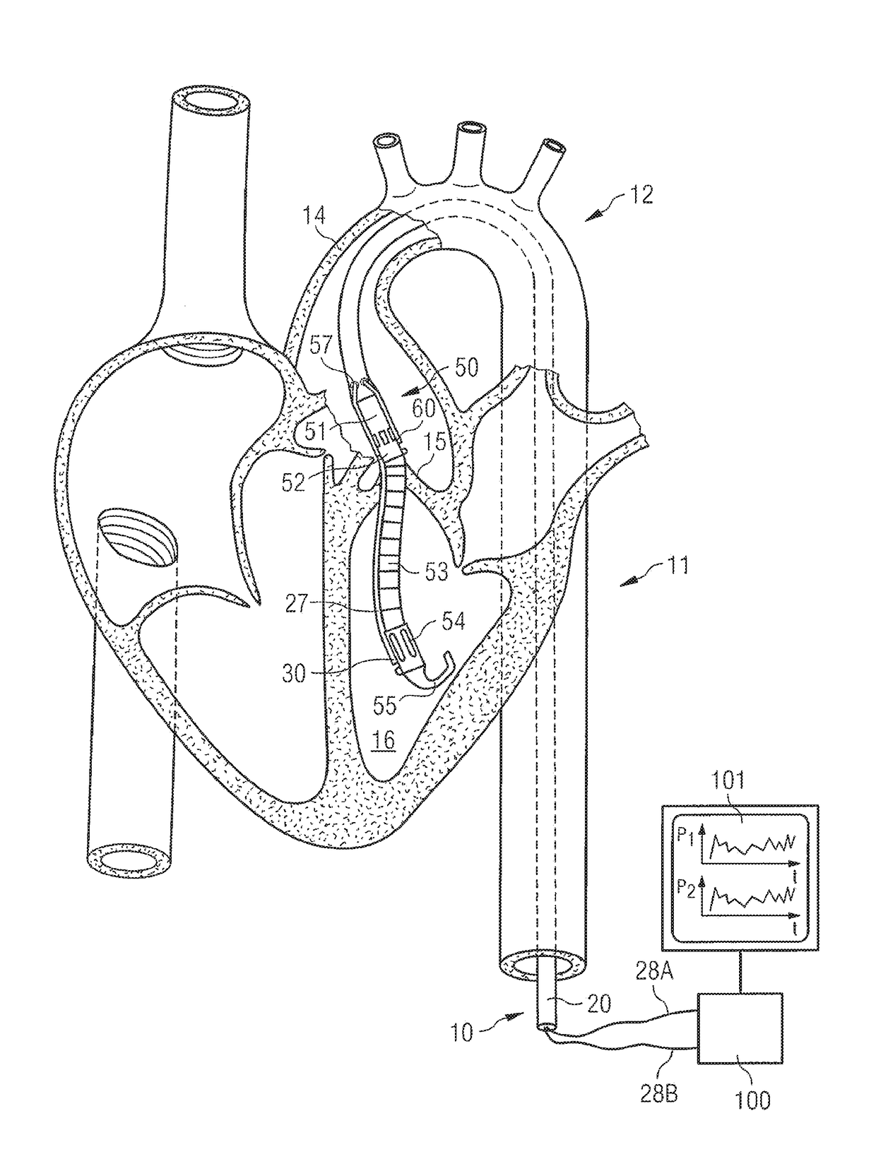
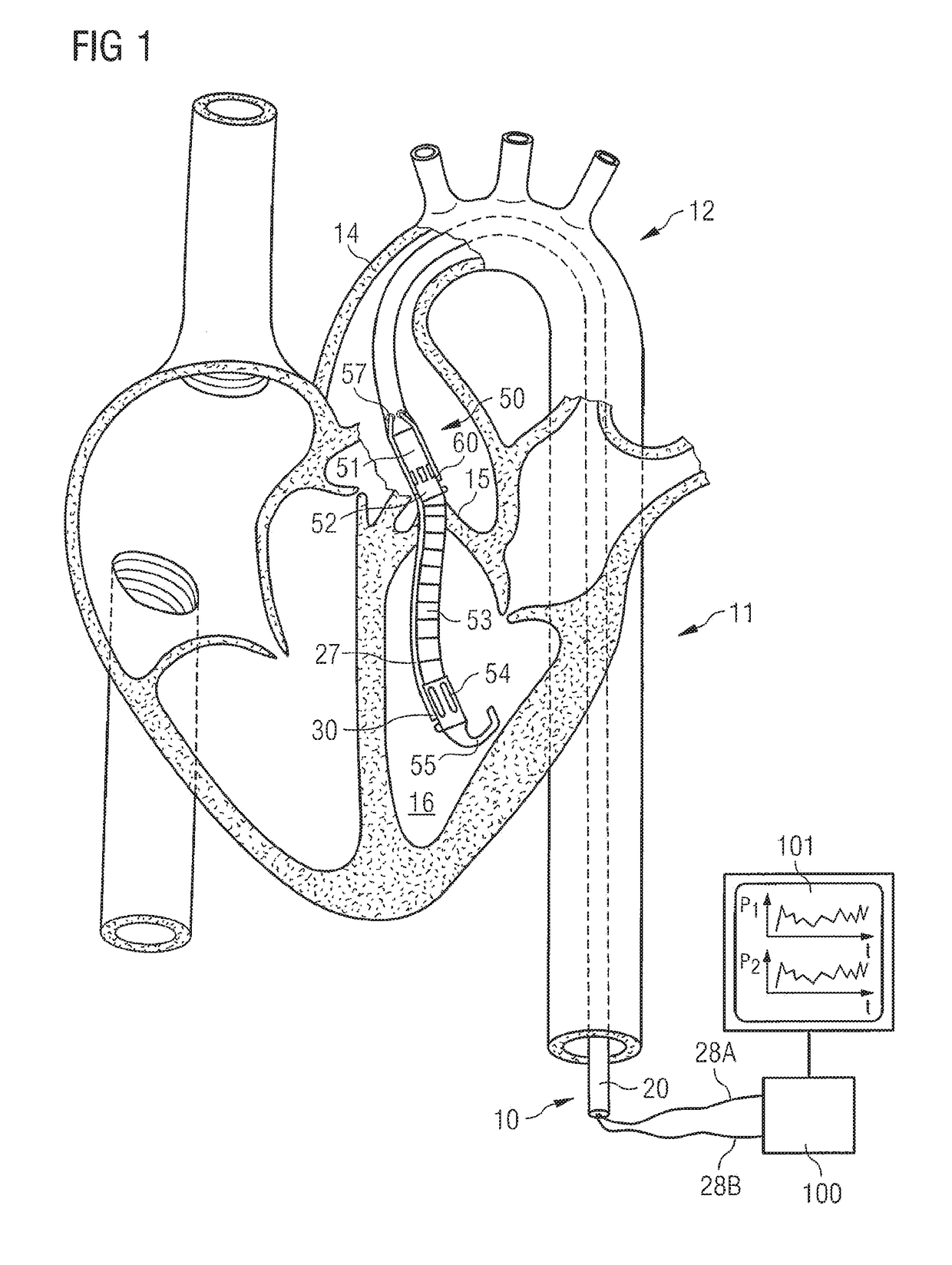
[0024]FIG. 1 shows an intravascular blood pump having a catheter 10 which is introduced into the descending aorta 11 retrograde. The descending aorta is part of the aorta 12 which first ascends from the heart and then descends and has the aortic arch 14. At the beginning of the aorta 12 there is located the aortic valve 15 which connects the left ventricle 16 to the aorta 12 and through which the intravascular blood pump extends. The intravascular blood pump comprises in addition to the catheter 10 a rotary pumping device 50 fastened at the distal end of the catheter hose 20 and having a motor section 51 and a pump section 52 disposed at an axial distance therefrom, as well as a flow cannula 53 protruding in the distal direction from the inflow end of the pump section 52 and having a suction inlet 54 located at its end. Distally of the suction inlet 54 there is provided a soft-flexible tip 55, which can be configured for example as a “pigtail” or in a J shape. Through the catheter h...


PUM


Abstract

A catheter (20), which can be part of an intravascular blood pump, possesses a kink sensor which extends over the total length of the catheter and comprises an optical fiber (28A). The optical fiber is attached to an evaluation device (100) which evaluates a preset light quantity transmitted through the optical fiber as to whether a part of the light quantity is coupled out of the optical fiber along the length of the optical fiber. This is interpreted as a kink event and displayed. The optical fiber preferably utilized for the kink sensor is the optical fiber of an optical pressure sensor.

Description

CROSS-REFERENCE TO RELATED APPLICATIONS[0001]This application is the U.S. National Stage of International Patent Application Number PCT / EP2013 / 058636, filed on Apr. 25, 2013, which claims priority to German Patent Application No. 10 2012 207 056.7, filed on Apr. 27, 2012. The entire contents of the foregoing applications are hereby incorporated herein by reference.TECHNICAL FIELD[0002]This invention relates in general to a system comprising a catheter, in particular a pressure-measuring catheter, and in particular to an intravascular blood pump having such a catheter system.BACKGROUND ART[0003]WO 2011 / 039091 A1 describes in connection with a heart support system a pressure-measuring catheter which has a catheter hose and a pressure sensor for measuring the pressure distally of the catheter hose. Concretely, the pressure-measuring catheter has an optical pressure sensor and an elongate tube made of metal or a high-strength plastic, for example PEEK, through which a loosely laid optic...

Claims


Application Information

Patent Timeline
Patent Type & Authority Patents(United States)
IPC IPC(8): A61M1/10A61B5/00A61B5/0215A61M25/01A61M1/12
CPCA61M1/1086A61B5/0215A61B5/02154A61B5/6852A61M1/125A61M25/01A61B2562/0233A61B2562/0247A61M2025/0166A61M2209/02A61M60/554A61M60/857A61M60/139A61M60/216A61M60/13A61M60/165A61M60/867A61M60/816A61M60/865Y10S415/90A61M60/148A61M2205/0266A61M2205/18
Inventor SPANIER, GERDSIESS, THORSTEN
Owner ABIOMED EURO
Why Eureka
Try Eureka