
Methods of varying low emission turbine gas recycle circuits and systems and apparatus related thereto

a low-emission, gas recycling technology, applied in mechanical equipment, sustainable transportation, machines/engines, etc., can solve the problems of increasing fuel demand, reducing power generation efficiency, and reducing power production, so as to improve operability and cost effectiveness, reduce power generation efficiency, and reduce the effect of power consumption

Active Publication Date: 2017-06-06
EXXONMOBIL UPSTREAM RES CO
View PDF737 Cites 4 Cited by
  • Summary
  • Abstract
  • Description
  • Claims
  • Application Information

AI Technical Summary

Benefits of technology

This approach enhances the operability and cost-effectiveness of low emission gas turbine systems by increasing CO2 concentration in the recycle stream, reducing oxygen levels, and minimizing equipment costs, leading to more efficient power generation and CO2 capture.

Problems solved by technology

However, both of these solutions are expensive and reduce power generation efficiency, resulting in lower power production, increased fuel demand and increased cost of electricity to meet domestic power demand.
In particular, the presence of oxygen, SOX, and NOX components makes the use of amine solvent absorption very problematic.
However, there are no commercially available gas turbines that can operate in such a cycle and the power required to produce high purity oxygen significantly reduces the overall efficiency of the process.
Capturing carbon dioxide from the exhaust of a gas turbine combined cycle power plant is very expensive for the following reasons: (a) the low concentration of carbon dioxide in the exhaust stack, (b) the large volume of gas that needs to be treated, (c) the low pressure of the exhaust stream, and the large amount of oxygen that is present in the exhaust stream.
All of these factors result in a high cost of carbon dioxide capture from combined cycle plants.

Method used


Image

  • Methods of varying low emission turbine gas recycle circuits and systems and apparatus related thereto
  • Methods of varying low emission turbine gas recycle circuits and systems and apparatus related thereto
  • Methods of varying low emission turbine gas recycle circuits and systems and apparatus related thereto

Examples


example 1

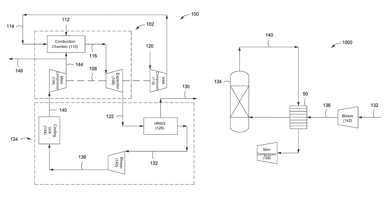
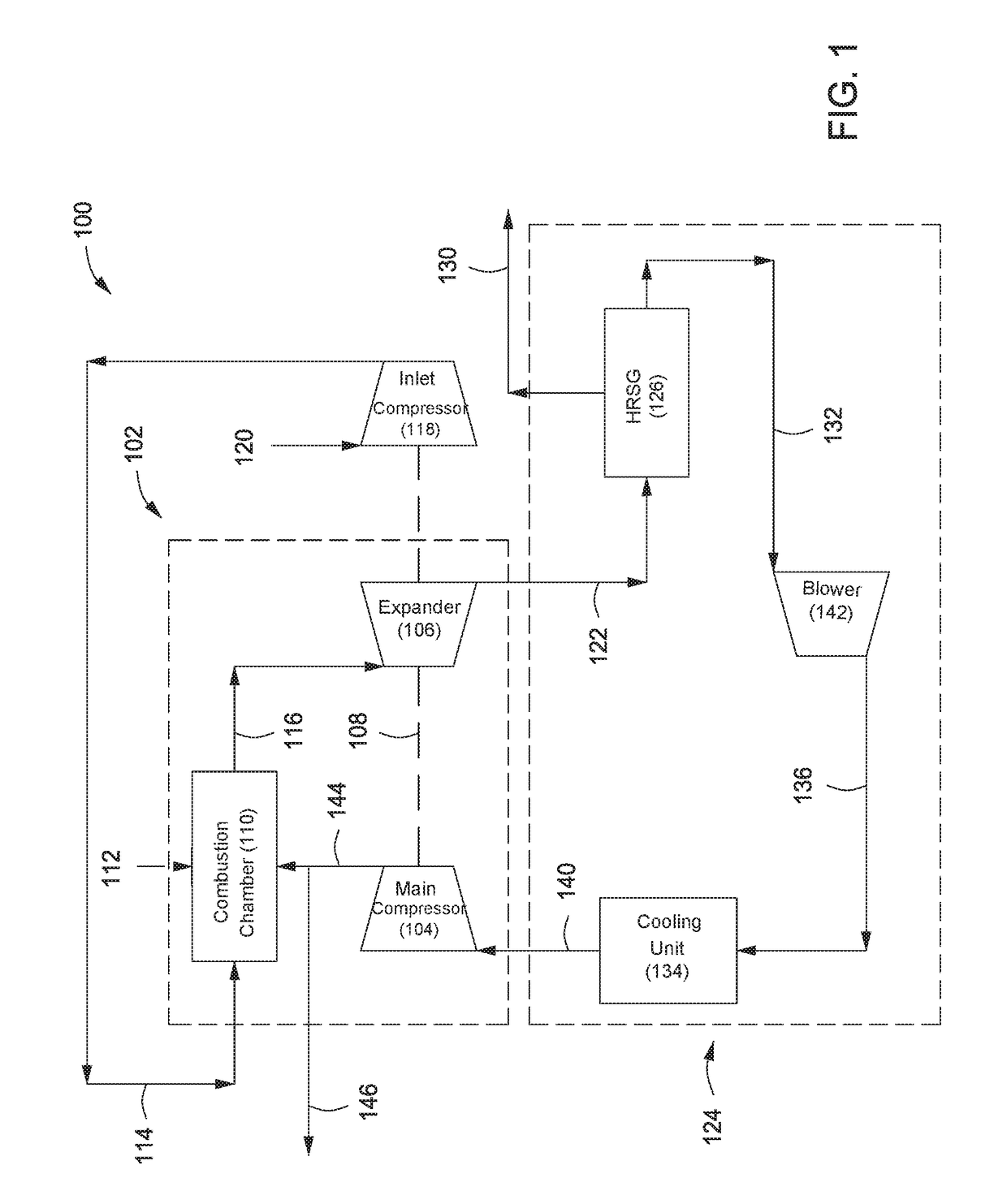
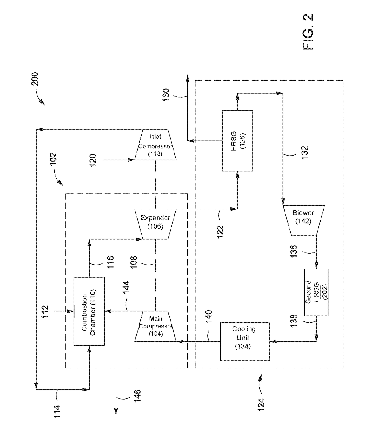
[0076]A study was performed to vary the exhaust gas recycle circuit of a low emission turbine. Several configurations corresponding to FIGS. 1-6 were simulated, and the results are reported in Table 1. The simulations and corresponding results are based on a single train case utilizing a frame 9FB combustion turbine generator (CTG) with air as the oxidant. The main air compressor (MAC) was assumed to be a single axial machine.

[0077]The following assumptions were used in all of the simulations of Example 1. The polytropic efficiency of the MAC was assumed to be 91% (no compressor curves used in simulation) and the polytropic efficiency of the exhaust gas blower was assumed to be 88.6%. The combustor outlet temperature and the expander inlet temperature were assumed to be 3200° F. and 2600° F., respectively. The minimum DCC outlet temperature was assumed to be 100° F. The flue gas battery limit pressure was assumed to be 1900 psig.

[0078]CTG performance was predicted using correlations...

example 2

[0084]A second study was performed to vary the exhaust gas recycle circuit of a low emission turbine. Several configurations corresponding to FIGS. 7-10 were simulated, and the results are reported in Table 3, along with comparison to a base case having the configuration of FIG. 1. The simulations and corresponding results are based on a single train case utilizing a frame 9FB combustion turbine generator (CTG) with air as the oxidant. The main air compressor (MAC) was assumed to be a single axial machine.

[0085]The following additional assumptions set forth in Table 2 were used in all of the simulations of Example 2.

[0086]

TABLE 2Polytropic efficiency of main compressor86.14%Polytropic efficiency of centrifugal booster 85.6%Polytropic efficiency of EGR compressor 92.5%(no compressor curves used in simulation)Polytropic efficiency of exhaust gas blower 88.6%Combustor outlet temperature3200° F.Expander inlet temperature2600° F.Polytropic efficiency of expander 84.2%Minimum DCC outlet t...


PUM


Abstract

Systems and methods are provided for varying the exhaust gas recycle circuit of low emission gas turbines. In one or more embodiments, the systems and methods incorporate alternatives to the use of a direct contact cooler. In the same or other embodiments, the systems and methods incorporate alternatives intended to reduce or eliminate the erosion or corrosion of compressor blades due to the presence of acidic water droplets in the recycled gas stream.

Description

CROSS REFERENCE TO RELATED APPLICATIONS[0001]This application is the National Stage entry under 35 U.S.C. 371 of PCT / US2012 / 027770, that published as WO 2012 / 128924 and was filed on 5 Mar. 2012 which claims the benefit of U.S. Provisional Application 61 / 542,035, filed on 30 Sep. 2011 and U.S. Provisional Application 61 / 466,381, filed Mar. 22, 2011, each of which is incorporated by reference, in its entirety, for all purposes.[0002]This application contains subject matter related to U.S. Provisional Application 61 / 542,039 filed Sep. 30, 2011 (PCT / US2012 / 027780, that published as WO 2012 / 128928 and was filed on 5 Mar. 2012); U.S. Provisional Application 61 / 542,041 filed Sep. 30, 2011 (PCT / US2012 / 027781, that published as WO 2012 / 128929 and was filed on 5 Mar. 2012; U.S. Provisional Application 61 / 542,037 filed Sep. 30, 2011 (PCT / US2012 / 027776, that published as WO 2012 / 128927 and was filed on 5 Mar. 2012); U.S. Provisional Application 61 / 542,036 filed Sep. 30, 2011 (PCT / US2012 / 027774,...

Claims


Application Information

Patent Timeline
Patent Type & Authority Patents(United States)
IPC IPC(8): F02C3/34F02C7/141
CPCF02C3/34F02C7/141F05D2260/95Y02E20/16Y02T50/60
Inventor MITTRICKER, FRANKLIN F.HUNTINGTON, RICHARD A.STARCHER, LOREN K.SITES, OMAR ANGUS
Owner EXXONMOBIL UPSTREAM RES CO
Learn More