Impurities removal system

a technology of impurities and removal systems, applied in the direction of separation processes, dispersed particle separation, chemistry apparatuses and processes, etc., can solve the problems of corroding parts, affecting the low-temperature aluminum members of heat exchangers, and inability to remove impurities by water spraying, etc., to achieve the effect of eliminating impurities in the exhaust gas

Active Publication Date: 2017-06-13
IHI CORP
View PDF17 Cites 1 Cited by
  • Summary
  • Abstract
  • Description
  • Claims
  • Application Information

AI Technical Summary

Benefits of technology

[0040]According to an impurity removal system of the disclosure, drain taken out from a cooler downstream of a compressor is used to produce an alkaline aqueous solution, so that the alkaline aqueous solution can be produced and supplied with no supply of water from outside. Thus, obtainable is an excellent effect that an alkaline aqueous solution may be used to effectively remove impurities in exhaust gas from an oxyfuel combustor even in a region where water is expensive or hardly available.

Problems solved by technology

However, the exhaust gas from the coal-fired boiler has less oxygen (O2) so that nitrogen (N) exists substantially in the form of nitrogen monoxide (NO) which is water-insoluble and thus is unremovable by water spraying or the like.
The above-mentioned sulfuric acid, hydrochloric acid and nitric acid are known to corrode parts in the exhaust gas treatment device; mercury, which is trace metal, is known to hurt low-temperature aluminum members constituting a heat exchanger.
There is also a problem that admixture of the impurities into the exhaust gas lowers a purity degree of the carbon dioxide, which makes troublesome the liquefaction of the carbon dioxide through compression and cooling and thus requires larger-sized equipment therefor.
Further, it is feared that any sulfur oxides admixed in carbon dioxide liquefied and stored in the ground may react with calcium in the ground to harm sealability of the storage.
Thus, the desulfurizer and the denitrator for removal of the impurities in the exhaust gas becomes extreme large in size, complicated in structure and increased in installation cost.
However, Patent Literature 2 also becomes complex in structure and increased in installation cost since the adsorptive purification unit is provided to remove impurities in exhaust gas from oxyfuel combustion.
Moreover, the adsorptive purification unit is troublesome in maintenance.

Method used


Image

  • Impurities removal system
  • Impurities removal system
  • Impurities removal system

Examples


Embodiment Construction

[0045]Embodiments of the disclosure will be described in conjunction with the attached drawings.

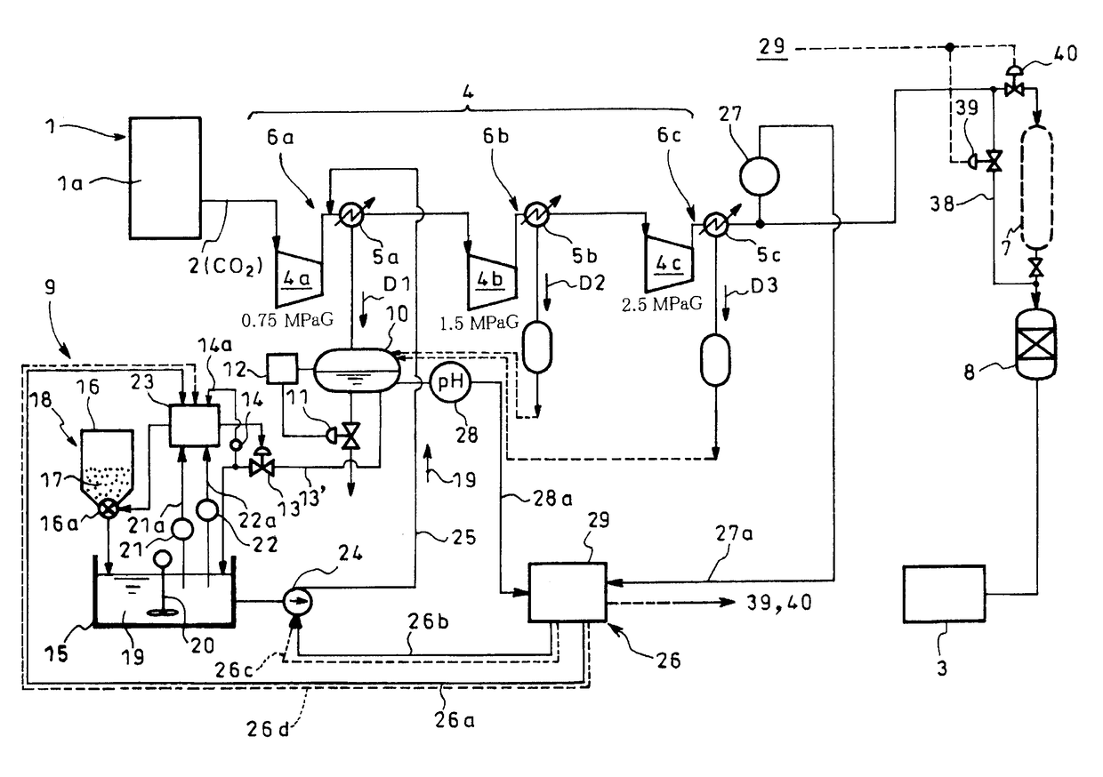
[0046]FIG. 1 is a systematic diagram showing an embodiment of an impurity removal system according to the disclosure provided for an oxyfuel combustor in which reference numeral 1 denotes an oxyfuel combustor such as a coal-fired boiler 1a for oxyfuel combustion of pulverized coal, exhaust gas 2 mainly constituted of carbon dioxide (CO2) being discharged from the oxyfuel combustor 1. For supply of the exhaust gas 2 mainly constituted of carbon dioxide from the oxyfuel combustor 1 to a liquefier 3 for liquefaction thereof, arranged downstream of the oxyfuel combustor 1 is a compression unit 4 for compression of the exhaust gas 2 to a predetermined target pressure, thereby providing an impurity removal system for removal of impurities in the exhaust gas 2.

[0047]The compression unit 4 in FIG. 1 comprises a plurality of (three in the embodiment illustrated) impurity separators 6a, 6b and 6c a...


PUM

PropertyMeasurementUnit
pressureaaaaaaaaaa
pressureaaaaaaaaaa
temperatureaaaaaaaaaa

Abstract

Provided are drain tank storing predetermined amount of drain from cooler; alkaline aqueous solution supply unit with aqueous solution adjustment tank receiving and storing part of drain in drain tank in predetermined amount, solid alkaline agent supplier supplying solid alkaline agent to produce alkaline aqueous solution, alkaline concentration controller controlling solid alkaline agent supplier to regulate alkaline concentration of alkaline aqueous solution, and pump supplying alkaline aqueous solution to exhaust gas entry side of cooler; and alkaline supply control unit with impurity sensor downstream of succeeding cooler, drain pH sensor obtaining detected pH of drain in drain tank, and supply controller controlling alkaline supply amount supplied to exhaust gas entry side of cooler based on detected impurity value to make detected pH to set value.

Description

TECHNICAL FIELD[0001]The present disclosure relates to an impurity removal system adapted to produce and supply an alkaline aqueous solution with no supply of water from outside when an exhaust-gas entry side of a cooler arranged downstream of a compressor for compression of exhaust gas from an oxyfuel combustor is supplied with the alkaline aqueous solution to discharge impurities in the exhaust gas together with drain.BACKGROUND ART[0002]Recently, an oxyfuel combustor has been reviewed as one of techniques for reducing emission of carbon dioxide (CO2) which is said to be one of factors for global warming, and attention has been attracted to, for example, a coal-fired boiler for oxyfuel combustion of pulverized coal. It has been conceived in the coal-fired boiler that oxygen in lieu of air is used as an oxidizing agent to produce combustion exhaust gas mainly composed of carbon dioxide. The exhaust gas mainly composed of carbon dioxide is compressed and cooled into liquefied or com...

Claims


Application Information

Patent Timeline
Patent Type & Authority Patents(United States)
IPC IPC(8): B01D53/78B01D53/00B01D53/50C01B32/50
CPCB01D53/78B01D53/002B01D53/504B01D2251/30B01D2251/304B01D2251/40B01D2251/402B01D2251/404B01D2251/602B01D2251/604B01D2251/606B01D2256/22B01D2257/80B01D2258/0283B01D2259/124
Inventor NAITO, TOSHIYUKI
Owner IHI CORP
Why Eureka
Try Eureka