Current balancing device for parallel battery cells in an electrified vehicle

a parallel battery cell and battery cell technology, applied in battery/fuel cell control arrangement, electrochemical generators, transportation and packaging, etc., can solve the problems of increasing parasitic chemical reactions within the battery cell(s), resistive losses, and unbalanced current magnitude of different parallel battery elements, so as to increase the response to the induced magnetic field, increase the magnetic permeability, and maximize the effect of field imbalan

Inactive Publication Date: 2017-06-20
FORD GLOBAL TECH LLC
View PDF7 Cites 1 Cited by
  • Summary
  • Abstract
  • Description
  • Claims
  • Application Information

AI Technical Summary

Benefits of technology

[0008]The variable resistances can be controlled by a wiper which rotates on a resistive surface or track as a result of the torque exerted on the permanent magnet. The potentiometer may have three terminals, including two end terminals and a common (tap) terminal. Two inversely proportional resistance values are established according to the position of the wiper on the resistive track. The resistance between an end terminal and the common terminal will increase while the resistance between the other end terminal and the common decreases, and vice-versa. The ratio between these two resistances is modulated by the rotation of the permanent magnet, which in turn is determined by the difference in magnetic field resulting from the cell current imbalance to be corrected. The variable resistances are small and can be chosen to compensate expected variation in DCIR over the life of the battery. For an increased response to the induced magnetic fields, the permanent magnet may be placed in or near gaps in magnetic cores receiving the power cables (e.g., a high magnetic permeability soft iron core, such as MetGlass). Various magnetic core geometries or configurations are possible to maximize response to field imbalances. The permanent magnet coupled to the potentiometer is made of a material with a magnetic coercive field chosen to maintain adequate performance under the surrounding demagnetizing field. The added variable resistances do not add resistive losses to the circuit since they are in parallel to the main power cables.

Problems solved by technology

Unlike a series connection which ensures that all cells carry the same magnitude of current, however, the current magnitude from different parallel battery elements can become unbalanced (i.e., unequal) due to differences between the DC internal resistances (DCIR) of the parallel elements.
The battery cell or string of cells having a lower DCIR will carry a higher current which leads to resistive losses and an increase in parasitic chemical reactions within the battery cell(s).
The charge capacity and ability to deliver power may be significantly degraded in the corresponding cells, adversely affecting battery life.
But such balancing has been difficult because the DCIR values can vary with time and with exposure to different environmental conditions such as temperature.
Complicated, expensive electronic circuits and controllers have been required for performing the current balancing.

Method used


Image

  • Current balancing device for parallel battery cells in an electrified vehicle
  • Current balancing device for parallel battery cells in an electrified vehicle
  • Current balancing device for parallel battery cells in an electrified vehicle

Examples


Embodiment Construction

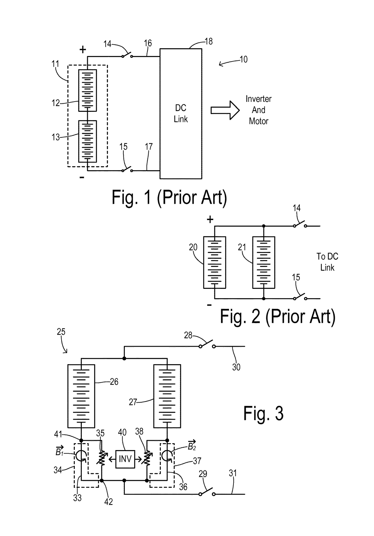
[0019]Referring to FIG. 1, an electric drive system 10 for a transportation vehicle includes a battery pack 11 with series-connected battery elements (e.g., cell strings) 12 and 13. Contactor switches 14 and 15 couple battery pack 11 to a positive bus 16 and negative bus 17, respectively, and to a DC link 18 for providing DC power to an inverter and motor / generator as known in the art. As shown in FIG. 2, it may alternatively be desirable to place battery elements 20 and 21 in parallel. The parallel elements provide a combined DC output to the buses via contactor switches 14 and 15 in order to deliver a high current level with less overall resistive losses (as compared to the series connection). Each battery cell or string of cells has a respective internal resistance (DCIR) which is in series with the current flowing through the respective battery element. In the parallel arrangement of FIG. 2, when the DCIR values of battery strings 20 and 21 diverge for any reason, then unequal c...


PUM


Abstract

A current equalizer is provided for first and second battery elements connected in parallel to supply a DC link. A first constant resistance carries a first current from the first battery element to the DC link. A first variable resistance is connected in parallel with the first constant resistance. A second constant resistance carries a second current from the second battery element to the DC link. A second variable resistance is connected in parallel with the second constant resistance. A balancer inversely adjusts the first and second variable resistances in response to relative magnitudes of the first and second currents. As a result, the total currents supplied from each battery element to the DC link are equalized because the effective total resistance in series with each battery element compensates for the difference in the internal battery resistances.

Description

CROSS REFERENCE TO RELATED APPLICATIONS[0001]Not Applicable.STATEMENT REGARDING FEDERALLY SPONSORED RESEARCH[0002]Not Applicable.BACKGROUND OF THE INVENTION[0003]The present invention relates in general to current balancing between parallel-connected battery strings in battery packs for electric vehicles, and, more specifically, to a self-adjusting circuit for pairwise balancing of the current from battery elements using a magnetic balance.[0004]Electric drives for hybrid (i.e., gas-electric) vehicles and for fully electric vehicles require a DC power source. The source typically is comprised of a battery. Common battery types such as lithium ion (Li-Ion) use a large number of cells stacked together into a battery pack. The output voltage and / or current capability of the battery pack can be greatly increased over the voltage and current provided by a single cell. Stacking of the cells can be done in series, in parallel, or a combination of the two. For example, two or more strings o...

Claims


Application Information

Patent Timeline
Patent Type & Authority Patents(United States)
IPC IPC(8): H02J7/00B60L11/18H02J7/34
CPCH02J7/0014B60L11/1866H02J7/34H01M10/4207H01M10/4257H01M2010/4271B60L58/22Y02T10/70Y02E60/10
Inventor POIRIER, ERIC
Owner FORD GLOBAL TECH LLC
Why Eureka
Try Eureka