Heater sensor complex with high thermal capacity

a sensor complex and high thermal capacity technology, applied in the field of heat exchanger and tip assembly, can solve the problems of poor workability of conventional soldering equipment, inconvenient use of soldering cartridges, and insufficient heat exchange, etc., to achieve accurate tip temperature sensing and control features, high thermal capacity, and high thermal capacity

Active Publication Date: 2017-07-11
HAKKO CO LTD
View PDF49 Cites 4 Cited by
  • Summary
  • Abstract
  • Description
  • Claims
  • Application Information

AI Technical Summary

Benefits of technology

[0010]The present invention discloses several designs for heater-sensor complexes or sub-assemblies for soldering cartridges and de-soldering systems having a high thermal capacity and accurate tip temperature sensing and control features. In the configurations of the present invention, the coil portion of the heater assembly is spaced proximally from the distal end of the subassembly to segregate the coil from the thermocouple temperature sensor. A solder tip for the cartridge may extend proximally to include a thick annular section surrounding the coil portion of the heater assembly to provide a high thermal capacity. The solder cartridges may include connector wires of dissimilar sizes and materials to couple the heater coil wire to the connections of a handle and the soldering station to reduce heat conduction to the handle.

Problems solved by technology

Therefore, in the field of soldering large parts that are designed for high currents, there is a problem in that the solder does not melt properly, or workability is very bad with conventional soldering equipment.
While the configuration according to the prior art U.S. Pat. No. 6,054,678 has been very well received and exceptionally adapted for use with small works, the soldering cartridges are not as well suited for use with large works, as for example the electrical parts for use in EVs and HEVs as well as power supply components such as power conditioners used in solar power generation.

Method used


Image

  • Heater sensor complex with high thermal capacity
  • Heater sensor complex with high thermal capacity
  • Heater sensor complex with high thermal capacity

Examples


Embodiment Construction

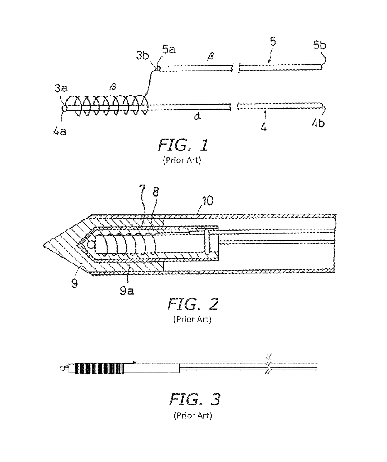
[0034]The design of the prior art heater-sensor sub-assembly and cartridge tip according to the prior art is described above with respect to FIGS. 1-3, and in detail in the U.S. Pat. No. 6,054,678 incorporated by reference herein. The design of the prior art heater-sensor sub-assembly for a soldering cartridge configured for use with a 70 Watt (W) power source is depicted in FIG. 3.

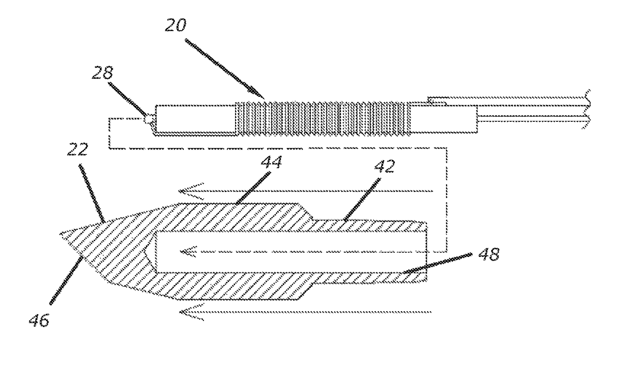
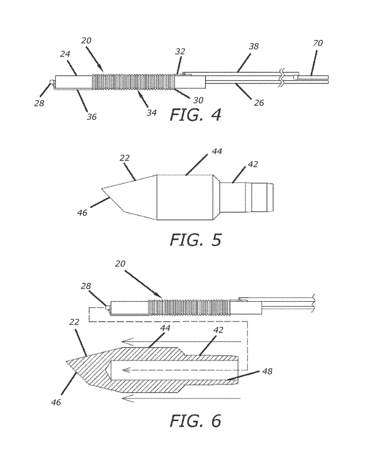
[0035]A solder cartridge according to the present invention includes a heater-sensor sub-assembly 20 according to a first embodiment of the present invention depicted in FIG. 4, and its associated heat conducting tip 22 is depicted in FIG. 5. The heater-sensor sub-assembly 20 includes an insulating pipe 24, return wire 26, thermocouple 28 and a heater wire 30. The heater wire 30 has a proximal portion 32 extending from a proximal location on the insulating pipe 24 to a coil 34, and a distal portion 36. The coil 34 is wound around the insulating pipe 24. The insulating pipe 24 preferably has an axial lengt...


PUM

PropertyMeasurementUnit
diameteraaaaaaaaaa
diameteraaaaaaaaaa
diameteraaaaaaaaaa

Abstract

The invention is directed to designs for heater-sensor sub-assemblies for soldering cartridges and de-soldering cartridges for soldering systems. The designs provide a high thermal capacity and accurate tip temperature sensing and control features. The coil portion of the heater assembly is spaced proximally from the distal end of the subassembly to segregate the coil from the thermocouple temperature sensor. The solder cartridges include connector wires of dissimilar sizes and materials to couple the heater coil wire to the connections of a handle and the soldering station to reduce heat conduction to the handle.

Description

BACKGROUND OF THE INVENTION[0001]Field of the Invention[0002]The present invention relates to a heater and tip assembly for use in soldering and desoldering systems. More specifically, the present invention relates to a heater-sensor subassembly for a soldering iron or desoldering tool for use environments requiring a soldering tip or desoldering tip with a high thermal capacity adapted for use in working electrical components designed to allow high current utilization.)[0003]Descriptions of Related Art[0004]Certain specialty automobile electrical parts for use in Electric Vehicles (EVs) and Hybrid Electric Vehicles (HEVs) as well as power supply components such as power conditioners used in solar power generation require very high thermal capacity when soldering because the required current flow to heat the soldering device is very high, and the parts to be soldered, sometimes referred to as the land of the substrate, are generally large and as a result the parts have a high therma...

Claims


Application Information

Patent Timeline
Patent Type & Authority Patents(United States)
IPC IPC(8): B23K37/00H05B3/00G01K7/02B23K3/03B23K3/08B23K3/02
CPCB23K3/026B23K3/02B23K3/03B23K3/08G01K7/02H05B3/00
Inventor MATSUZAKI, KENJITAKEUCHI, HITOSHIMOCHIZUKI, TOSHIZAKI
Owner HAKKO CO LTD
Why Eureka
Try Eureka