
Plasma generator

Active Publication Date: 2017-07-11
BERLIN EVGENIJ VLADIMIROVICH +1
View PDF13 Cites 0 Cited by
  • Summary
  • Abstract
  • Description
  • Claims
  • Application Information

AI Technical Summary

Benefits of technology

This patent describes a method for creating a plasma in a controlled environment, which can improve efficiency, increase the purity of plasma, and reduce contamination. This is achieved by using a conductive screen that prevents unwanted discharges and a coil that generates high-frequency fields. By reducing the distance between the screen and the plasma, the coil and plasma can communicate better, and a special dielectric filler can help reduce interference between them. The result is a more reliable and efficient plasma generation process.

Problems solved by technology

A disadvantage of the known device is unstable operation and low efficiency caused by the fact that alternating magnetic field penetrates through the housing on side of plasma generator or behind it that can lead to unstable spurious discharge.
The known technology has the following disadvantages: limited scope of application due to the limitation of minimum possible size of working chamber.
For example, if the working chamber is a cylinder and the coil is located on its axis, the desired plasma concentration generated is 1012 cm−3, minimum diameter of working chamber is 180 mm larger than the diameter of the coil, low efficiency of application of high frequency current energy to generate plasma in that part of the working chamber where it is required.
This is due to the fact that high-frequency fields penetrate into the volume of the working chamber not only where it is required to generate plasma used in the process, but also where they cause spurious discharge obstructing maintaining steady operation of device and causing undesired plasma on those surfaces where it is not required, low reliability as high-frequency fields fill a larger volume than is required, the known device has a large leakage inductance, which leads to excessively high voltage on the coil, which in turn may lead to etching of dielectric.
A disadvantage of the known device is the low efficiency and low operating reliability due to the fact that the screen is located closer to the coil than plasma that leads to an increase in current flowing through the coil and a strong increase in ohmic losses in the screen.

Method used


Image

  • Plasma generator
  • Plasma generator
  • Plasma generator

Examples


second embodiment

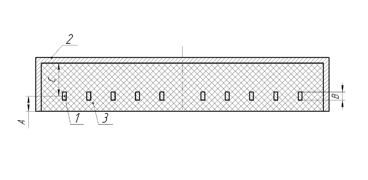
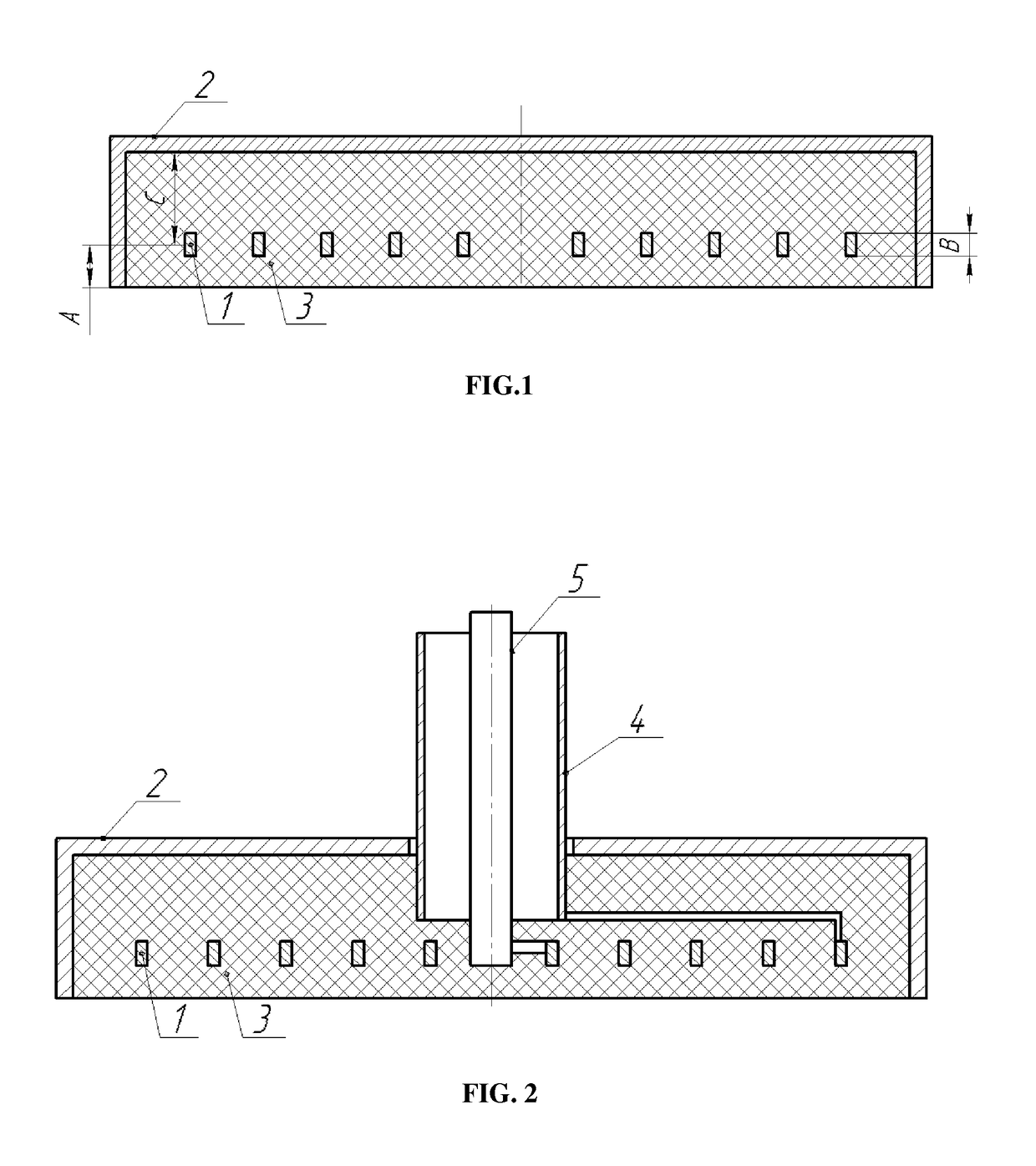
[0053]Plasma generator of second embodiment has flat coil 1.

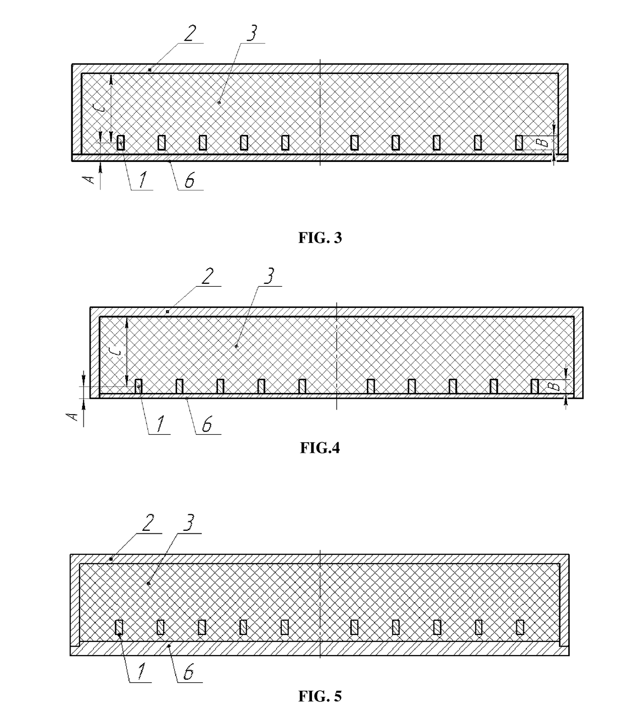
[0054]Flat coil design ensures simultaneously maximum inductive coupling between coil and plasma and minimal inductive coupling between coil and screen within given size of device.screen 2 is designed as a ring which axis is perpendicular to plane of the coil, the edge of the ring facing the volume, where it is required to generate plasma, is enclosed with dielectric. The ring is made of conductive material (e.g., aluminum or aluminum alloy).screen ring design can limit (localize) the scope of high-frequency electromagnetic fields, which increases the efficiency of power input to plasma in working volume, prevents the occurrence of spurious discharge around the device that leads to useless energy losses and reduces the stability and reliability of operation. Also, the use of screen of well conductive material (e.g. aluminum) allows to avoid interference in the surrounding parts of the working chamber and tooling that often ...

third embodiment

[0055]Plasma generator of the third embodiment has the screen electrically connected to one end of the coil. The permittivity of dielectric between the coil windings and between the coil and the screen is in the range of 2.5 to 50.

[0056]Use of dielectric of 2.5 to 50 dielectric capacitivity increases the capacitance of the coil to the screen, connected to one end of the coil that can partially compensate coil self-inductance, to reduce high frequency current required to power the device and to reduce energy losses in power supply circuits. The use of dielectric with dielectric constant of less than 2.5 will not lead to significant increase in capacitance and of higher than 50 will lead to substantial increase of interturn capacitance.

[0057]In addition, plasma generators of all three embodiments have dielectric that separates coil from the working surface of the device made of material resistant to plasma. The outer surface of insulator is closed by at least one dielectric screen mad...


PUM

PropertyMeasurementUnit
Temperatureaaaaaaaaaa
Thicknessaaaaaaaaaa
Densityaaaaaaaaaa

Abstract

The invention relates to devices intended for treatment of materials in gas discharge plasma of low temperature, namely the induction plasma generator, placed inside the process volume (working chamber). The technical problem to be solved by the proposed invention is to increase the efficiency of the device; to improve the reliability of the device, increase purity of plasma environment and increase density of plasma generated; increase the life of device; reduce the level of noise; reduce the size of the device.

Description

RELATED APPLICATIONS[0001]This application claims priority to International Application No. PCT / RU2013 / 000263, filed on Mar. 28, 2013, and incorporated herewith by reference in its entirety.FIELD OF THE INVENTION[0002]The invention relates to devices intended for treatment of materials in low temperature plasma of gas discharge, namely the inductive plasma generator, placed inside the process volume (working chamber).BACKGROUND OF THE INVENTION[0003]There is a device for plasma processing comprising an inductively coupled plasma source that is located inside the processing chamber, consisting of an antenna placed in a dielectric spacer, while the antenna and spacer are placed in a sealed insulating housing. (U.S. Pat. No. 5,580,385, MΠκ (C23C16 / 00, C23C16 / 50, published Mar. 12, 1996)[0004]A disadvantage of the known device is unstable operation and low efficiency caused by the fact that alternating magnetic field penetrates through the housing on side of plasma generator or behind i...

Claims


Application Information

Patent Timeline
IPC IPC(8): C23C16/50H01J37/32H01J37/04
CPCH01J37/3211H01J37/04H01J37/321H01J2237/002H01J2237/036
Inventor BERLIN, EVGENIJ VLADIMIROVICHGRIGORYEV, VASILY JURYEVICH
Owner BERLIN EVGENIJ VLADIMIROVICH
Learn More