Mass spectrometer and mass spectrometry method

a mass spectrometer and mass spectrometry technology, applied in the direction of electron/ion optical arrangement, particle separator tube details, instruments, etc., can solve the problems of low accuracy of the peak area value in the extracted ion chromatogram, and the inability to achieve the highest level of quantitative accuracy and sensitivity. , to achieve the effect of improving the accuracy and sensitivity of quantitative analysis

Active Publication Date: 2017-08-15
SHIMADZU CORP
View PDF13 Cites 0 Cited by
  • Summary
  • Abstract
  • Description
  • Claims
  • Application Information

AI Technical Summary

Benefits of technology

[0034]With the mass spectrometer and mass spectrometry method according to the present invention, the SN ratio of the detection signal for a target component in a sample improves. Therefore, for example, it is possible to improve the accuracy and sensitivity of a quantitative analysis based on a chromatogram corresponding to the target compound. Consequently, it becomes possible to determine the quantity of a trace amount of component which could not have been detected by conventional methods.

Problems solved by technology

However, conducting a measurement under the control parameters adjusted in this manner does not always ensure that the highest level of quantitative accuracy and sensitivity is achieved.
In such a case, the accuracy of the peak area value in the extracted ion chromatogram will be low.

Method used


Image

  • Mass spectrometer and mass spectrometry method
  • Mass spectrometer and mass spectrometry method
  • Mass spectrometer and mass spectrometry method

Examples


Embodiment Construction

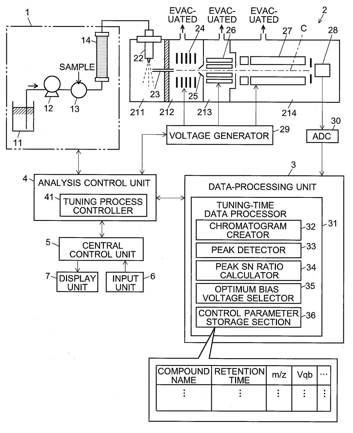
[0040]One embodiment of the liquid chromatograph mass spectrometer (LC-MS) which includes a mass spectrometer according to the present invention is hereinafter described with reference to the attached drawings. FIG. 1 is a configuration diagram showing the main components of the LC-MS of the present embodiment.

[0041]The liquid chromatograph unit 1 includes a mobile-phase container 11, pump 12, injector 13 and column 14. In this liquid chromatograph unit 1, the pump 12 draws a mobile phase from the mobile-phase container 11 and supplies it to the column 14 at a fixed flow rate. The injector 13 injects a fixed amount of sample into the mobile phase at a predetermined timing. The injected sample is carried into the column 14 by the stream of the mobile phase. While the sample is passing through this column 14, the compounds (sample components) contained in the sample are separated, to be eventually eluted from the exit port of the column 14 in a temporally separated form.

[0042]The mass...


PUM

PropertyMeasurementUnit
pressureaaaaaaaaaa
mass spectrometryaaaaaaaaaa
mass-to-charge ratiosaaaaaaaaaa

Abstract

The degree of ion dissociation which occurs within a first intermediate vacuum chamber (212) maintained at a comparatively low degree of vacuum depends not only on the amount of energy of the ion but also on the size and other properties of the ion. Accordingly, a predetermined optimum level of DC bias voltage is applied to an ion guide (24) so as to create, within the first intermediate vacuum chamber (212), a DC electric field which barely induces the dissociation of an ion originating from a target compound in a sample while promoting the dissociation of an ion originating from a foreign substance which will form a noise signal in the observation of the target compound. The optimum DC bias voltage is previously determined by creating extracted ion chromatograms based on data collected under various DC bias voltages and evaluating the SN ratio using the chromatograms. Consequently, the accuracy and sensitivity of the quantitative determination is improved as compared to a conventional system in which only the signal strength of the target compound is considered.

Description

CROSS REFERENCE TO RELATED APPLICATIONS[0001]This application is a National Stage of International Application No. PCT / JP2013 / 083702 filed Dec. 17, 2013, the contents of all of which are incorporated herein by reference in their entirety.TECHNICAL FIELD[0002]The present invention relates to a mass spectrometer and mass spectrometry method, and more specifically, to a mass spectrometer and mass spectrometry method suitable for a liquid chromatograph mass spectrometer including a liquid chromatograph (LC) combined with a mass spectrometer. The term “mass spectrometer” includes a mass spectrometer capable of an MS / MS analysis, such as a tandem quadrupole mass spectrometer.BACKGROUND ART[0003]In general, a quantitative analysis of a target component in a sample using a liquid chromatograph mass spectrometer (LC-MS) is performed as follows: A selective ion monitoring (SIM) measurement or multiple reaction monitoring (MRM) measurement for a mass-to-charge ratio corresponding to an ion ori...

Claims


Application Information

Patent Timeline
Patent Type & Authority Patents(United States)
IPC IPC(8): H01J49/00G01N30/72H01J49/06H01J49/16
CPCH01J49/005G01N30/7266H01J49/0031H01J49/0045H01J49/063H01J49/165
Inventor ASANO, NATSUYO
Owner SHIMADZU CORP
Why Eureka
Try Eureka