Ignition system for low grade synthesis gas at high compression

a synthesis gas and high compression technology, applied in the direction of combustion gas production, machines/engines, mechanical equipment, etc., can solve the problems of high thermal conversion efficiency of biomass, carbon monoxide rich synthesis gas is generally more difficult to burn in an internal combustion engine than a hydrogen rich gas, and hydrogen has an unusually high flame speed, etc., to achieve high thermal efficiency

Inactive Publication Date: 2017-08-22
V GRID ENERGY SYST INC
View PDF26 Cites 5 Cited by
  • Summary
  • Abstract
  • Description
  • Claims
  • Application Information

AI Technical Summary

Benefits of technology

[0009]Although the exemplary embodiments set forth herein involve the use of single cylinder engine, the igniter system set forth herein can be applied to an engine of any size, such as comprising 1-16 cylinders, 0.1 to 5 liters per cylinder and any functional compression ratio. For a reciprocating piston internal combustion engine having one or more cylinders, each cylinder can be fitted with an igniter system with at least one igniter per cylinder.

Problems solved by technology

However, hydrogen production typically involves the water shift reaction which requires high temperature and absorbs substantial reaction energy.
This may result in higher thermal conversion efficiency from biomass to combustible gas, however, carbon monoxide rich synthesis gas is generally more difficult to burn in an internal combustion engine than a hydrogen rich gas.
Both carbon monoxide and hydrogen are rated as high octane fuels, but hydrogen has an unusually high flame speed because of its small molecular size and high reaction energy.

Method used


Image

  • Ignition system for low grade synthesis gas at high compression
  • Ignition system for low grade synthesis gas at high compression
  • Ignition system for low grade synthesis gas at high compression

Examples


Embodiment Construction

[0015]In the following paragraphs, embodiments of the present invention will be described in detail by way of example with reference to the attached drawings. Throughout this description, the preferred embodiment and examples shown should be considered as exemplars, rather than as limitations on the present invention. As used herein, the “present invention” refers to any one of the embodiments of the invention described herein, and any equivalents. Furthermore, reference to various feature(s) of the “present invention” throughout this document does not mean that all claimed embodiments or methods must include the referenced feature(s).

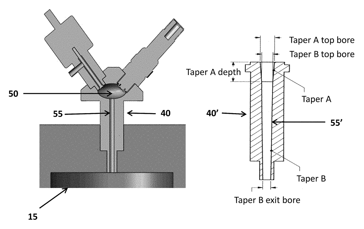
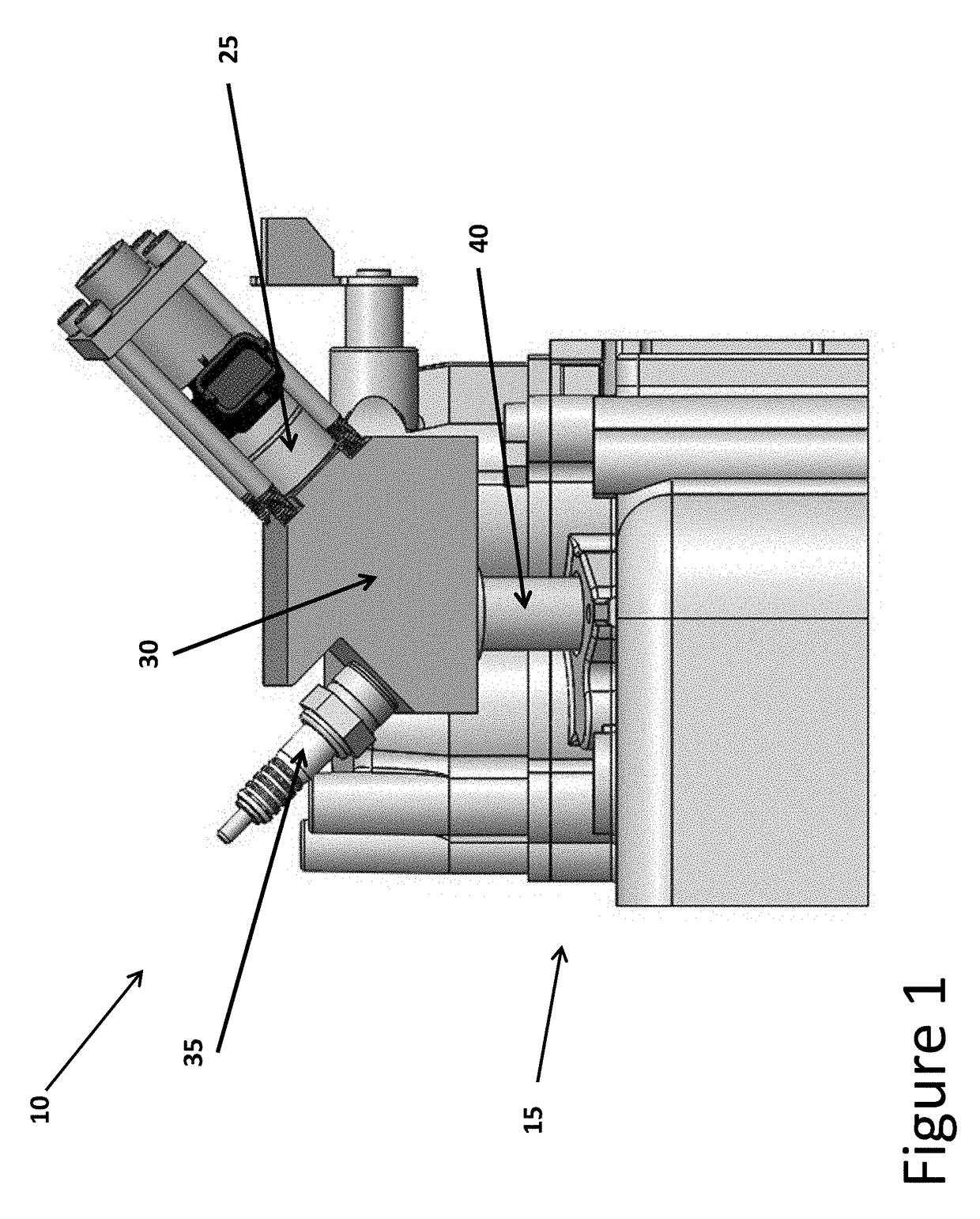
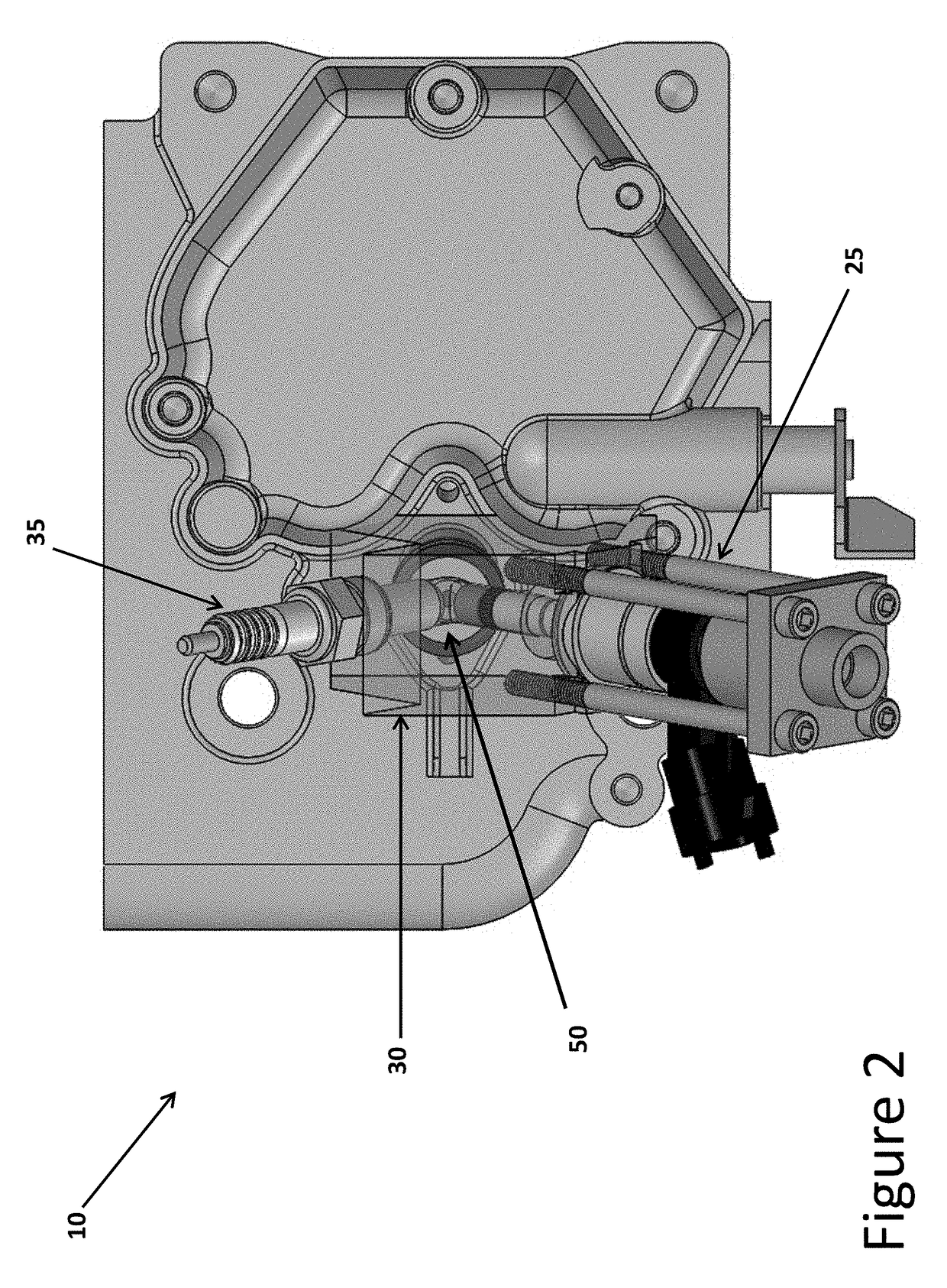
[0016]Referring to FIGS. 1-3, an igniter system and process for combusting low grade carbon monoxide rich synthesis gas in high compression engines at high thermal efficiency will now be described. In particular, FIG. 1 is a perspective view illustrating an igniter system 10 on a host engine cylinder head 15 of a main cylinder of an engine having one o...


PUM


Abstract

An igniter system for a reciprocating piston internal combustion engine having one or more cylinders including at least one igniter per cylinder is disclosed. The igniter system can comprise: a combustion chamber connected to a main cylinder of the engine by a restricted diameter bore, wherein a lean burn fuel mixture is introduced into the combustion chamber by the normal compression stroke of the engine; a hydrogen valve that injects a hydrogen rich gas into the combustion chamber forming a mixture of hydrogen and air having a hydrogen concentration above the stoichiometric ratio for hydrogen and air in the combustion chamber; and a spark ignition source that injects hot unburned hydrogen into the main cylinder, thereby initiating ignition.

Description

RELATED APPLICATIONS[0001]This application claims priority to U.S. Provisional Patent Application No. 61 / 856,235 filed on Jul. 19, 2013, the content of which is incorporated herein by reference in its entirety.FIELD OF THE INVENTION[0002]The invention broadly relates to ignition applications and, more particularly, to an ignition system for low grade synthesis gas at high compression.BACKGROUND OF THE INVENTION[0003]Biomass is a low cost readily available energy source that is useful for the generation of other energy types such as electricity or liquid fuel. Biomass derived energy has the added advantage that it is intrinsically carbon neutral and can also be carbon negative when residual processed carbon is placed in the ground for long term storage.[0004]A popular intermediate product of biomass energy conversion is synthesis gas, which is produced by the high temperature partial combustion of the material. Devices which support the gasification of biomass are typically called ga...

Claims


Application Information

Patent Timeline
Patent Type & Authority Patents(United States)
IPC IPC(8): F02B19/10F02B43/04F02B7/08F02B43/10F02B19/12F02B19/02
CPCF02B19/1019F02B7/08F02B19/1004F02B19/108F02B19/1014F02B43/04F02B43/10F02B19/02F02B19/12F02B2043/106Y02T10/125Y02T10/32F02B43/08C10J3/20C10J2300/165Y02T10/12Y02T10/30
Inventor CHEIKY, MICHAEL
Owner V GRID ENERGY SYST INC
Why Eureka
Try Eureka